Convertible multi-diameter sleeve for optical fiber connectors

a multi-diameter, optical fiber technology, applied in optics, printed circuits, instruments, etc., can solve the problems of difficult to realize stable optical loss and retention with the sleeve, and achieve the effect of minimizing optical loss at the connection point and precise meeting of the cor

Inactive Publication Date: 2003-03-06
TONAMI ELECTRONICS CORP +1
View PDF0 Cites 25 Cited by
  • Summary
  • Abstract
  • Description
  • Claims
  • Application Information

AI Technical Summary

Benefits of technology

[0054] The connection of optical fiber cables with different diameter plug ferrules using the invented sleeve can be completed simply by inserting the plug ferrules into the ends of the sleeve and is just as easy as connecting using existing sleeves. Furthermore, even if plug ferrules with different diameters are inserted into the invented sleeve, the optical fiber core will be positioned correctly and the core will not be bent, so the fibers will be connected accurately and firmly while keeping the cores precisely joined thereby minimizing optical loss at connections.[0055] If the slots on the sleeve extend along the entire length of the sleeve, as in existing sleeves, internal stresses cannot be completely eliminated and optical loss and retention ability vary slightly. The slots of the invented sleeves do not extend the whole length of the sleeve and so internal distortion will be removed completely by heat treatment, making it possible to supply stable convertible multi-diameter sleeves. FIGS. 1 and 2 show a first set of the slots 18 extend only part way along the length of the larger diameter portion 16 and a second set of the slots extend only part way along the length of the smaller diameter portion 17. Moreover, FIGS. 1 and 2 show the slots 18 along the portion 16 are longitudinally parallel but radially offset with the slots 18 along the portion 17 (a radius from the longitudinal axis to a slot of the portion 16 does not fall within the same plane as any radius from the longitudinal axis to a slot of the portion 17). FIG. 3 shows the slot 18 extends the length of only the portion 16.[0056] The invented sleeve described in the second embodiment has slots at both ends positioned at points of symmetry based on the axis which makes connection of optical fiber cables more accurate, firm and keeps the cores more precisely joined.[0057] FIG. 3a shows the slot 18a extending along portion 17 and the diameter change portion 15a while the slot 18b extends along portion 16.[0058] It should be apparent that embodiments other than those specifically described above come within the spirit and scope of the present invention. Thus, the present invention is not defined by the above-described embodiments but is defined by the appended claims.

Problems solved by technology

However, the difference between the diameters of the ends of the sleeves creates internal stress in the sleeve and it is difficult to realize stable optical loss and retention with the sleeve.

Method used


Image

  • Convertible multi-diameter sleeve for optical fiber connectors
  • Convertible multi-diameter sleeve for optical fiber connectors
  • Convertible multi-diameter sleeve for optical fiber connectors

Examples


first embodiment

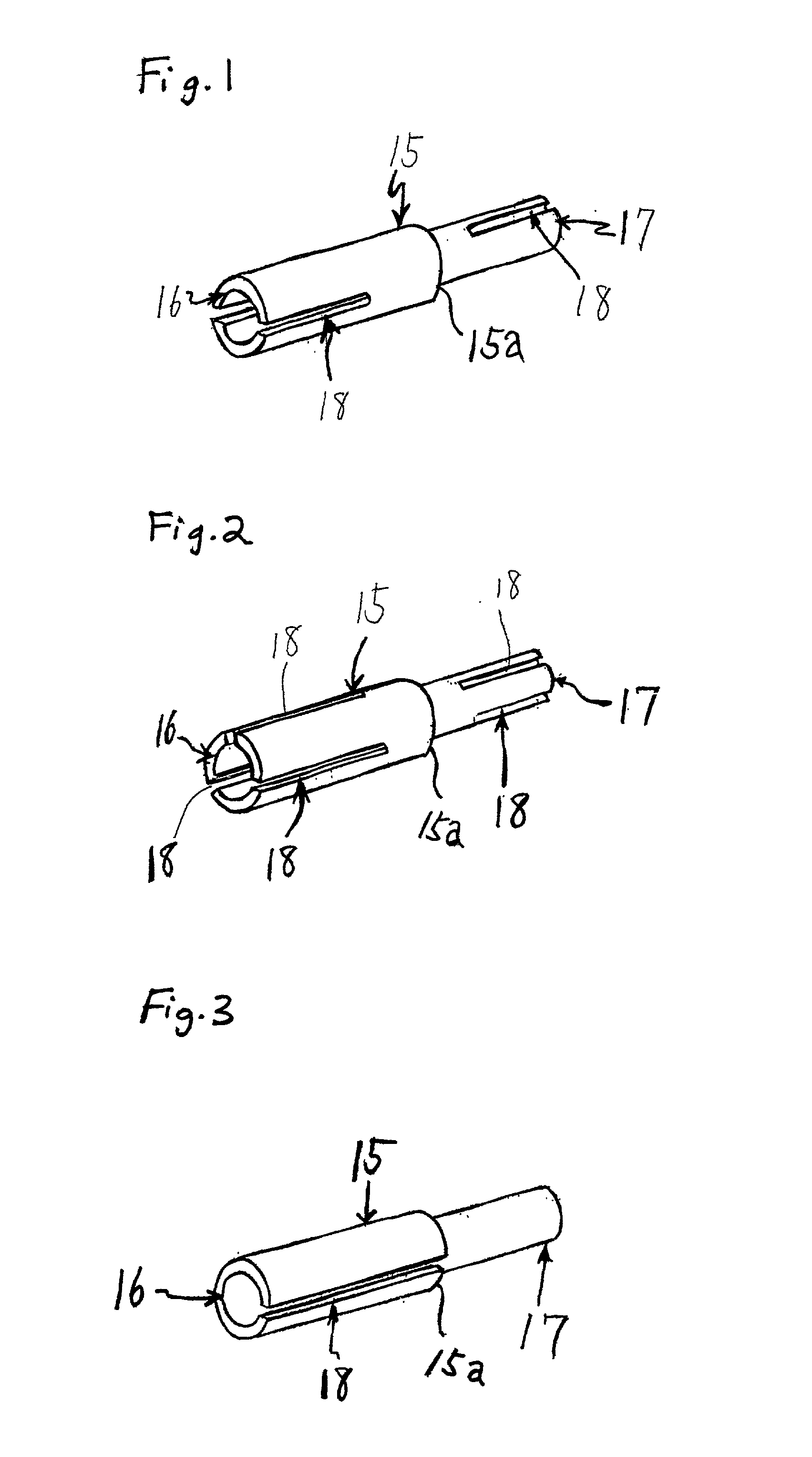
[0043] FIG. 1 shows the invention. The figure shows a sleeve (15) which is made by cutting and grinding materials used for springs such as phosphor bronze, beryllium copper, high-carbon steel and stainless steel or made of other above-described materials. The sleeve (15) has a cylindrical shape with different inner and outer diameters on the left and right ends. As shown in the figure, the sleeve has a larger diameter portion (16), a smaller diameter portion (17), and diameter change portion (15a) which is taper shaped. Diameter change portion (15a) is frustoconical, but other taper shapes may be employed. Also, the present invention permits embodiments where only inner walls of diameter change portion (15a) are tapered. There are slots (18) of specified length parallel to the axis in the ends of the larger diameter portion (16) and the smaller diameter portion (17). Each end has two slots positioned diametrically opposite of each other and the slots at one end are in a plane at nin...

fourth embodiment

[0048] FIG. 3a shows a side view of the present invention. FIG. 3a shows in the case of the slot length extending 100% of the length of the respective portion, the slot 18a of the smaller diameter portion may further extend to the terminal of the diameter change portion 15a, but the slot 18b of the larger diameter portion 16 does not extend into the diameter change portion 15a.

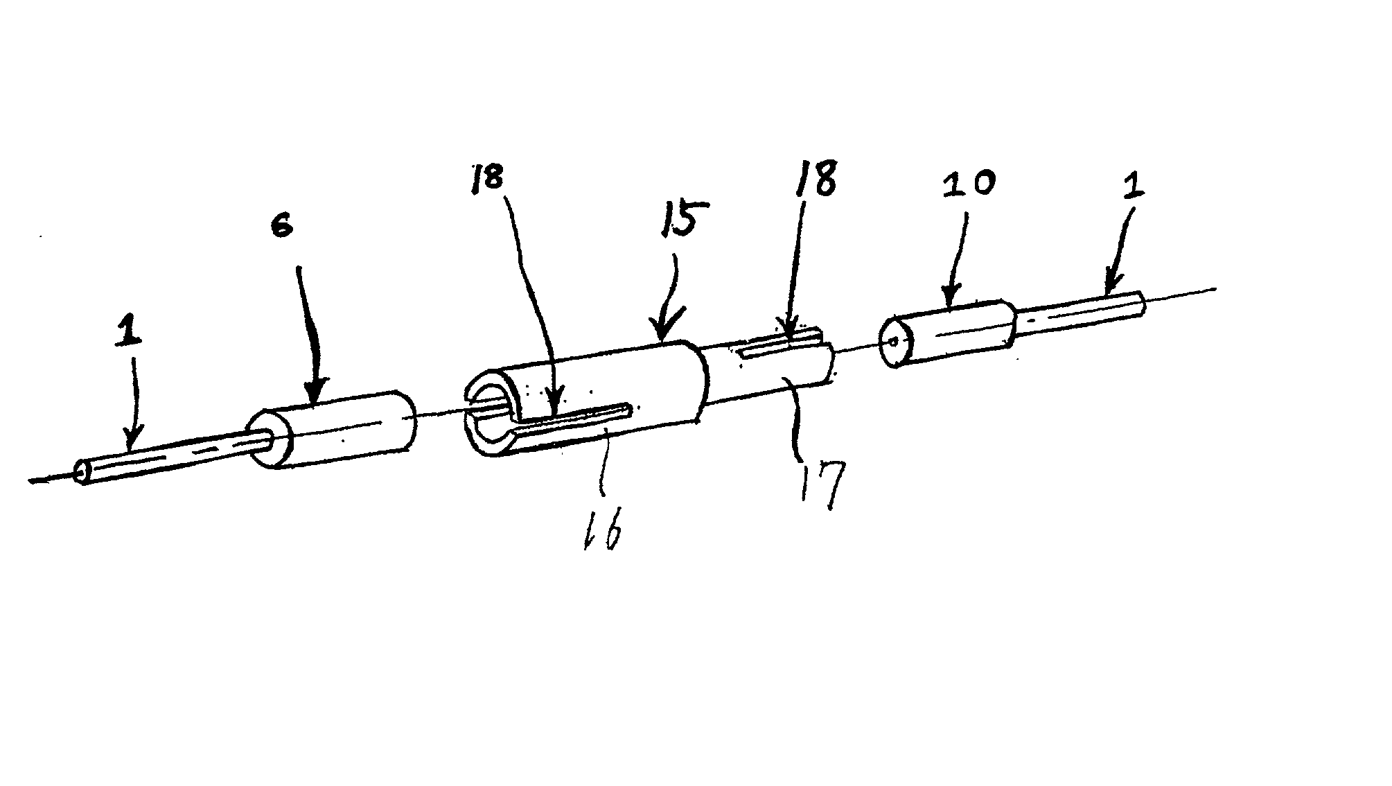
[0049] FIG. 4 shows a perspective view to explain connection of optical fiber cables using the sleeve described in the first example of use of the invention.

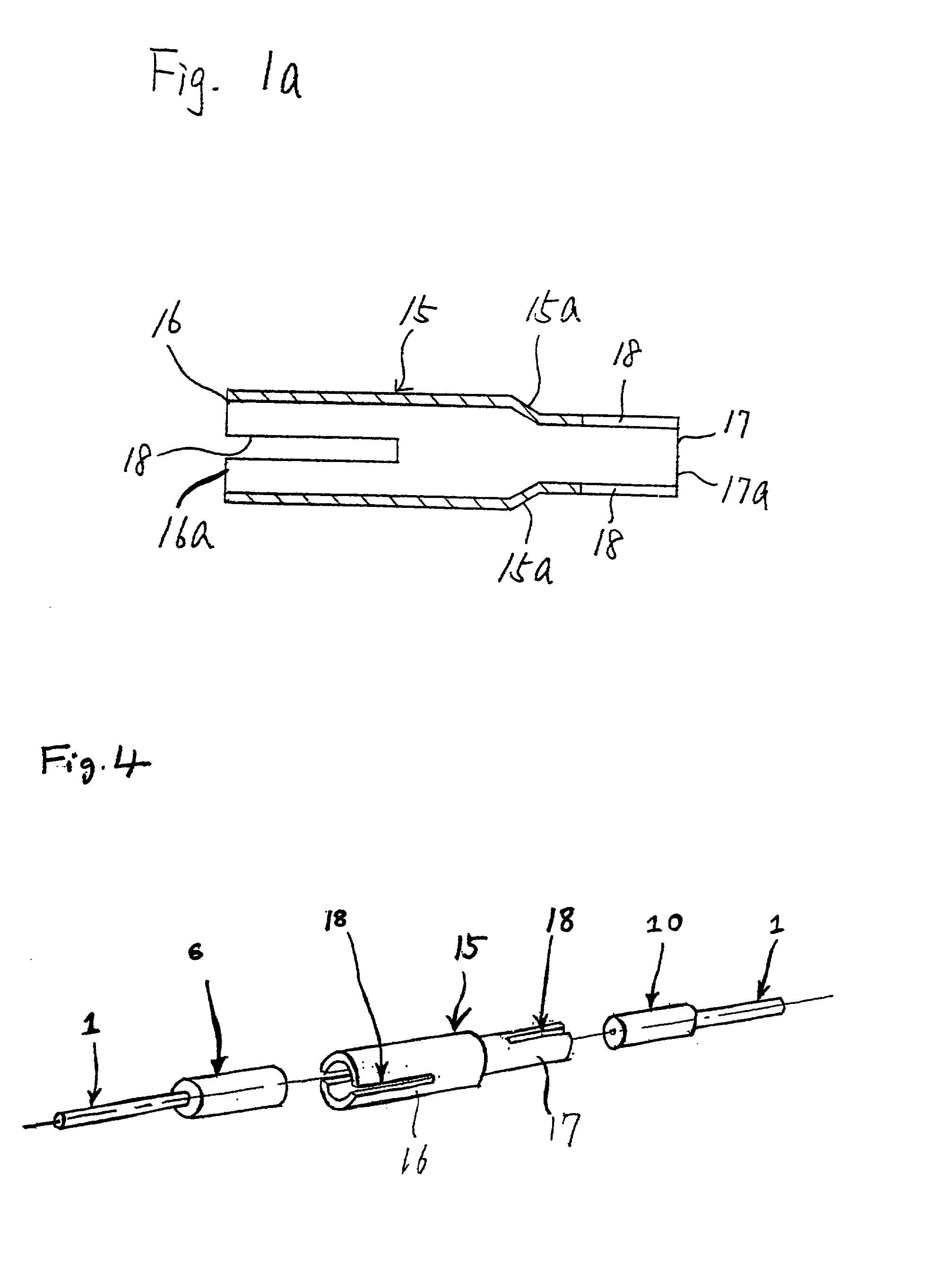
[0050] FIG. 4a shows a cross-sectional view of the sleeve of FIG. 4 wherein diameter change portion (15a) of the sleeve, at which the diameter of the sleeve changes, is tapered.

[0051] To connect plug ferrules with different diameters using the invented sleeve (15) of any of FIGS. 1-3a, insert the larger plug ferrule (6) on the end of an optical fiber (1) into the larger diameter portion (16) of the sleeve (15) and insert the smaller plug ferrule (10) of an...

second embodiment

[0056] The invented sleeve described in the second embodiment has slots at both ends positioned at points of symmetry based on the axis which makes connection of optical fiber cables more accurate, firm and keeps the cores more precisely joined.

[0057] FIG. 3a shows the slot 18a extending along portion 17 and the diameter change portion 15a while the slot 18b extends along portion 16.


PUM


Abstract

This invention is a convertible multi-diameter sleeve for optical fiber connectors to allow optical fiber cables with plug ferrules of different internal and external diameters to be pushed into the sleeve and connected with precise core alignment keeping stable conditions. The sleeve has at least one slot extending part way along the length of the sleeve.

Description

I. FIELD OF THE INVENTION[0001] This invention is a convertible multi-diameter sleeve for optical fiber connectors to allow optical fiber cables with plug ferrules of different internal and external diameters to be connected with precise core alignment.II. BACKGROUND DESCRIPTION[0002] Optical fibers are used to transfer communications and data which use the medium of light. An example of the above-mentioned optical fiber cable with a single core (1) is shown in FIG. 5. The optical fiber consists of the fiber core (4), (composed of (2) the core of fibers made of highly pure quartz glass, etc., with different refractive indices, and (3) cladding), and the external sheathing (5) made of nylon and ultraviolet-hardened plastic which covers the fiber core (4).[0003] Optical fiber cables (1) described above are manufactured in various lengths. Fibers are joined together in a semi-permanent bond to produce the length of optical fiber required when the optical fiber cable is laid, but optica...

Claims


Application Information

Patent Timeline
Patent Type & Authority Applications(United States)
IPC IPC(8): G02B6/38
CPCG02B6/3877
Inventor SAITOH, KEN
Owner TONAMI ELECTRONICS CORP
Why Eureka
Try Eureka