Fuel injection valve

a fuel injection valve and fuel injector technology, applied in the direction of fuel injection apparatus, fuel feed system, spraying apparatus, etc., can solve the problems of fuel injector, limited design options for components, and high danger of coking contamination

Inactive Publication Date: 2003-03-13
ROBERT BOSCH GMBH
View PDF5 Cites 4 Cited by
  • Summary
  • Abstract
  • Description
  • Claims
  • Application Information

AI Technical Summary

Problems solved by technology

One disadvantage of the fuel injector known from German Patent 41 31 499 C1 is the position of the swirl-creating element downstream from the sealing seat.
The danger of contamination from coking is great, especially in the case of directly injecting fuel injectors.
Particular attention must paid in the design to ruggedness of the swirl-producing elements; this limits the design options for the component, since minimum requirements for material thickness for example must be adhered to.
A further disadvantage is that the location downstream from the sealing seat causes a dead volume to be formed, from which fuel can escape after the injection operation ends.
This afterdripping results in incomplete and uncontrolled combustion, which produces a large amount of pollu

Method used


Image

  • Fuel injection valve
  • Fuel injection valve
  • Fuel injection valve

Examples


Embodiment Construction

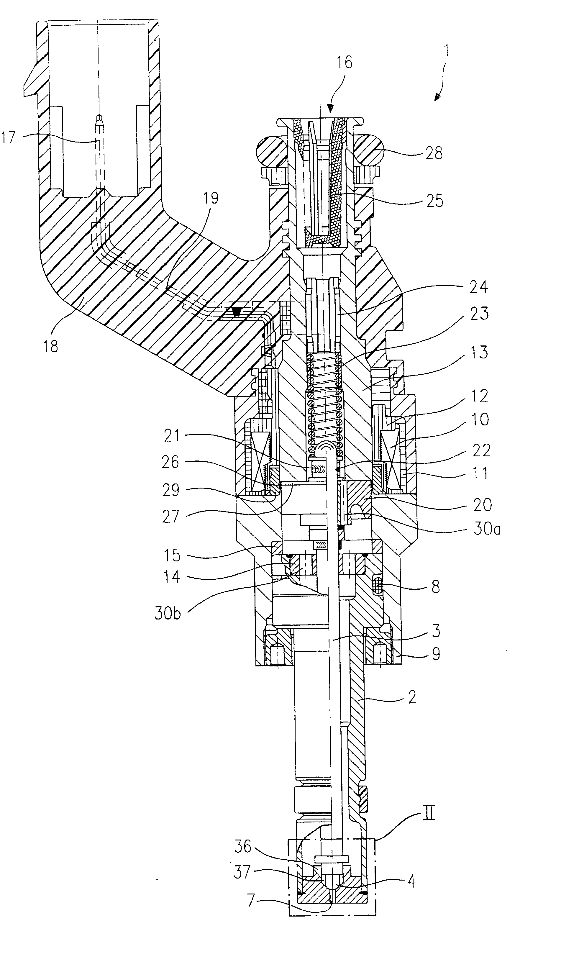
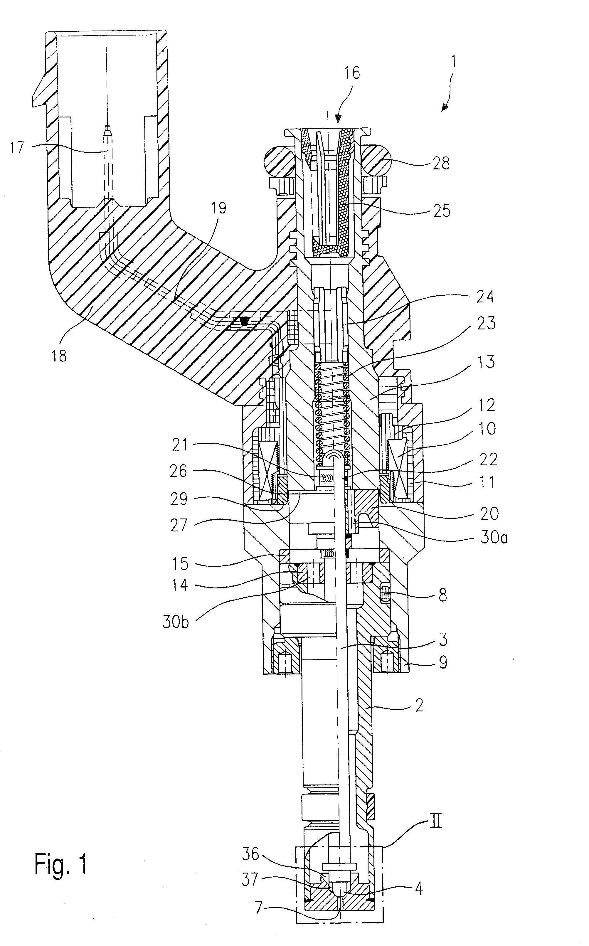
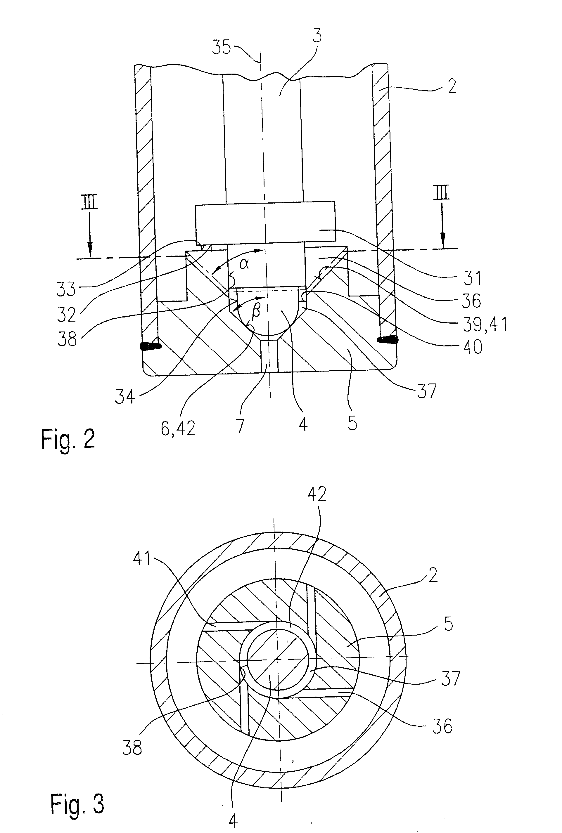
[0019] Before describing an embodiment of a fuel injector 1 according to the present invention with reference to FIGS. 2 and 3, the essential components of the fuel injector 1 according to the present invention will now be explained briefly in an overall view for a better understanding of the presentation with reference to FIG. 1.

[0020] Fuel injector 1 is designed in the form of a fuel injector 1 for fuel injection systems of engines having fuel mixture compression and spark ignition. Fuel injector 1 is suitable in particular for direct injection of fuel into the combustion chamber (not shown) of an engine.

[0021] Fuel injector 1 includes a nozzle body 2 in which a valve needle 3 is situated. Valve needle 3 is mechanically linked to a valve-closure member 4, which cooperates with a valve-seat surface 6 on a valve-seat member 5 to form a sealing seat. In this embodiment, fuel injector 1 is an electromagnetically operated fuel injector 1 which has an injection orifice 7. Nozzle body 2 ...


PUM


Abstract

A fuel injector for fuel injection systems of internal combustion engines includes a valve needle and a valve-closure member mechanically linked to it, which cooperates with a valve-seat surface situated in a valve-seat member to form a sealing seat, and at least one swirl-producing element which is situated upstream from the sealing seat in the valve-seat member. One or more swirl channels which are open toward the upstream side of the valve-seat member are incorporated into the upstream side of the valve-seat member as a swirl-producing element.

Description

BACKGROUND INFORMATION[0001] The present invention relates to a fuel injector according to the preamble of the main claim.[0002] Fuel injectors in which swirl-producing elements are incorporated into a valve-seat member are known for example from German Patent 41 31 499 C1. The swirl-producing element is implemented in the form of grooves which are incorporated into the valve-seat member and discharge into an injection orifice. The metering of the volume of fuel to be injected is accomplished by the cross section of the injection orifice. The injection orifice is located either in the valve-seat member or in a perforated disk which is situated at the downstream end of the fuel injector.[0003] An additional fuel injector in which the swirl is produced by grooves is known from German Patent 42 31 448 C1. The swirl-producing elements are located upstream from the sealing seat and are incorporated in the form of grooves in a central recess of the valve-seat member which is used to guide...

Claims


Application Information

Patent Timeline
IPC IPC(8): F02M51/08F02M61/18F02M61/16
CPCF02M61/162
Inventor DANTES, GUENTER
Owner ROBERT BOSCH GMBH
Why Eureka
Try Eureka