Chromatography column

a technology of chromatography and assembly, which is applied in the direction of heating element shapes, components, lighting and heating apparatus, etc., can solve the problems of frequent breakage of the capillary column or of the conductive coating deposited thereon, complicated and laborious, and prove far from suitable for withstanding high temperatures, and achieve the effect of optimal temperature distribution

Inactive Publication Date: 2003-03-20
THERMO FINNIGAN ITALA
View PDF11 Cites 2 Cited by
  • Summary
  • Abstract
  • Description
  • Claims
  • Application Information

AI Technical Summary

Benefits of technology

0012] These objects are achieved by the present invention, which relates to a direct-heating column assembly for chromatography, of the type comprising at least one capillary column and at least one element made of electrically conductive material in contact with the capillary column, characterised in that the element made of conduct

Problems solved by technology

However, on account of the different coefficients of thermal expansion of the materials, there occur frequent breakages of the capillary column or of the conductive coating deposited thereon.
A construction of this kind, in addition to being particularly complicated and lab

Method used


Image

  • Chromatography column
  • Chromatography column
  • Chromatography column

Examples


Embodiment Construction

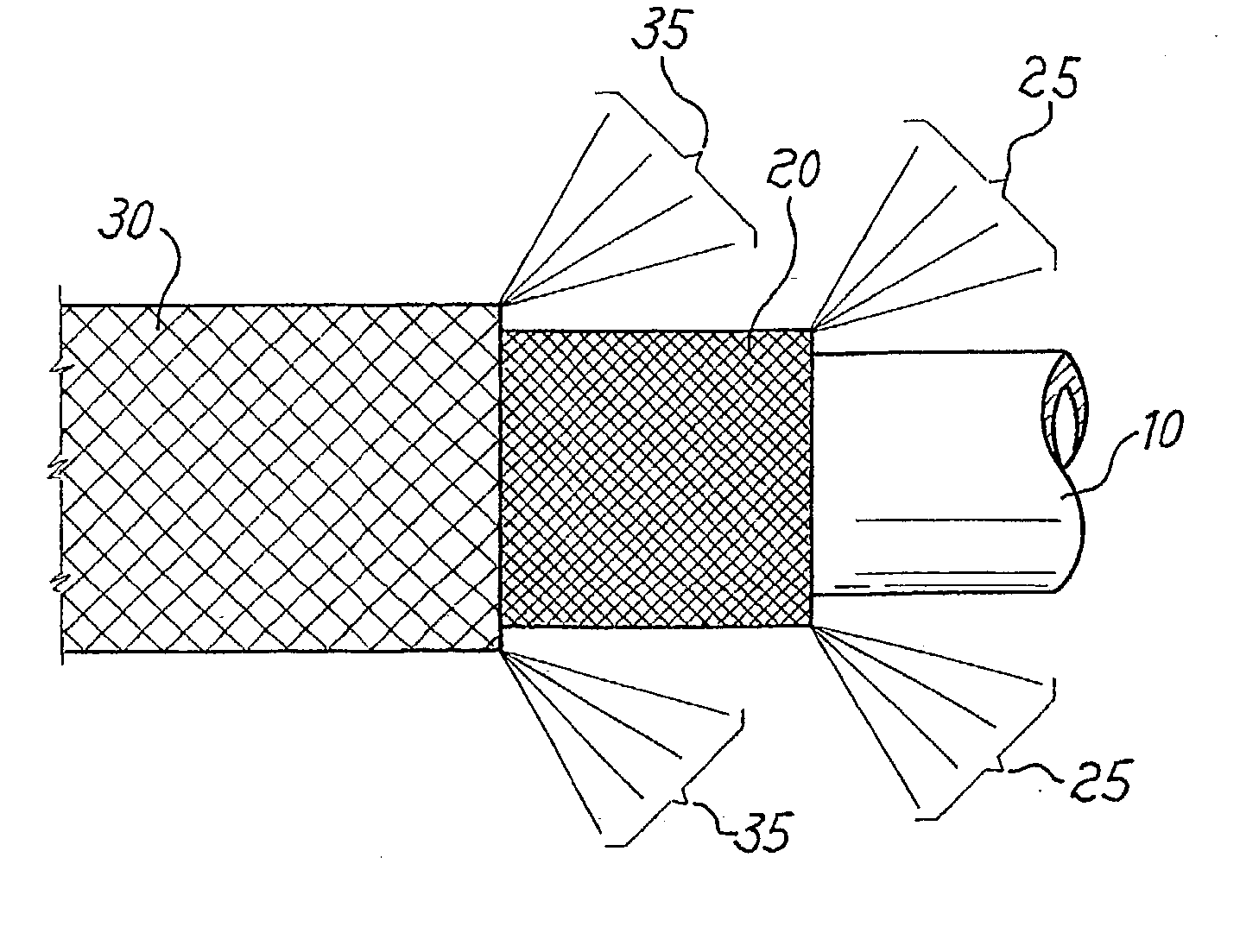
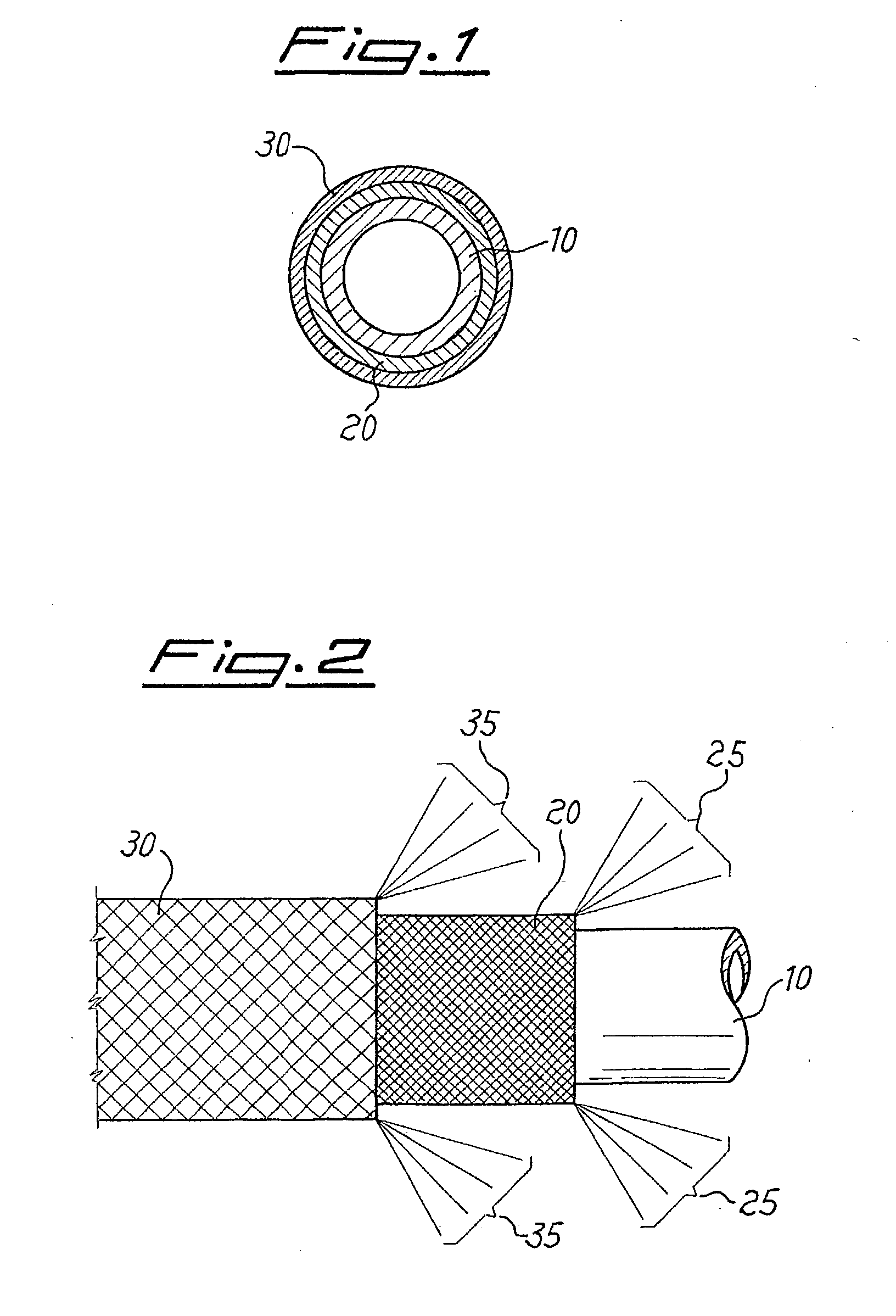
[0030] With reference firstly to FIGS. 1 and 2, a column assembly according to the present invention comprises a capillary column 10, made, for example, of fused silica, enveloped in a tubular mesh 20 made of electrically conductive material. The tubular mesh 20 is in turn surrounded by a tubular sheath 30 made of insulating material.

[0031] As an alternative to the embodiment here illustrated purely by way of example, the capillary column 10 can also be made of metal, for instance steel or other suitable conductive metals; and be coated externally with insulating material, consisting, for example, of a polyamide sheath, to prevent contact between the metal capillary column and the tubular mesh 20.

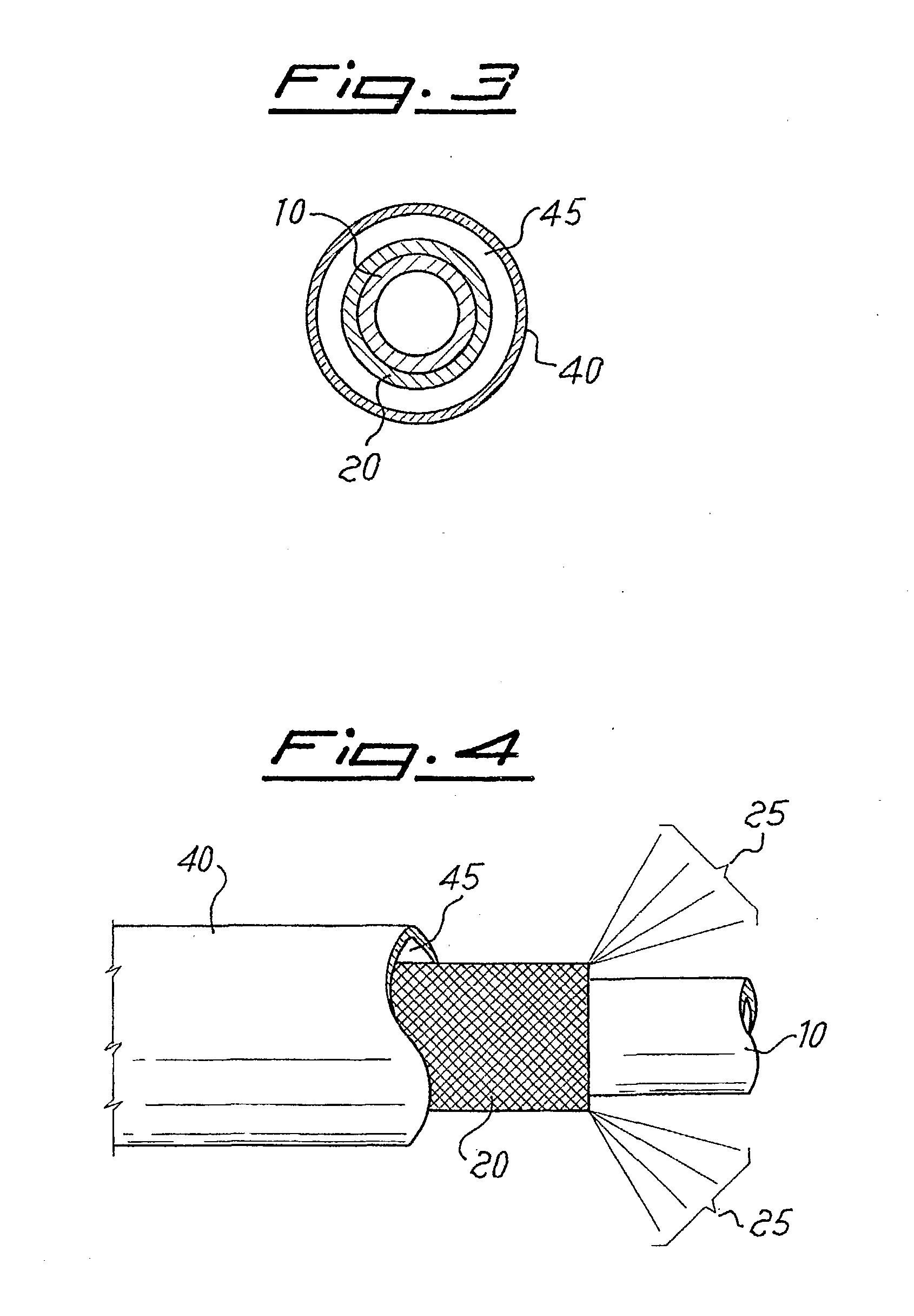
[0032] The tubular mesh 20 is formed by weaving together a plurality of thin filaments 25 made of an electrically conductive material, such as nickel, or anyway any material, whether metallic or non-metallic, having suitable characteristics of electrical conductivity.

[0033] As compared to t...


PUM


Abstract

Described herein is a direct-heating column assembly for chromatography, in which a capillary column is enveloped in a tubular mesh formed by a plurality of woven filaments.

Description

[0001] The present invention relates to a chromatography column and, more in particular, a chromatography-column assembly of the direct-heating type.[0002] A number of technical solutions are already known in which the capillary column is subjected to direct heating by means of an electrically conductive element which is set in contact with the capillary column and electrically powered in a controlled way.[0003] Such an approach makes it possible to obtain various advantages, among which the considerable reduction in the electrical energy required for heating the capillary column and the rapid response of the system to the temperature programs that are set in the course of the analysis.[0004] A number of the various possibilities of obtaining direct heating of the column are, for example, illustrated in U.S. Pat. No. 5,808,178 and in the corresponding international patent application No. WO 97 / 14957 in the name of Thermedics. Among the various solutions proposed, an assembly is illu...

Claims


Application Information

Patent Timeline
IPC IPC(8): G01N30/30
CPCG01N30/30G01N2030/3061
Inventor MAGNI, PAOLOZILIOLI, GIACINTOFACCHETTI, RICCARDO
Owner THERMO FINNIGAN ITALA
Why Eureka
Try Eureka