Magnetoresistive magnetic field sensors and motor control devices using same

Inactive Publication Date: 2003-03-27
INTERNATIONAL RECTIFIER COEP
View PDF7 Cites 60 Cited by
  • Summary
  • Abstract
  • Description
  • Claims
  • Application Information

AI Technical Summary

Problems solved by technology

Such current sensors are subject to several disadvantages, especially when used with motor controllers.
For example, current transformers are frequency sensitive, and in any event, occupy substantial space, while Hall Effect devices requires use of toroids which exhibit hysteresis and limited bandwidth.
Measuring voltage across a reference element is also not completely satisfactory due to insertion loss in the sensing element, problems with signal couplers, etc.
However, known MR sensing elements exhibit some undesirable properties.
Among these are excessive responsiveness to stray magnetic and electric fields, narrow range of linearity (making measurement over a large curr

Method used


Image

  • Magnetoresistive magnetic field sensors and motor control devices using same
  • Magnetoresistive magnetic field sensors and motor control devices using same
  • Magnetoresistive magnetic field sensors and motor control devices using same

Examples


Embodiment Construction

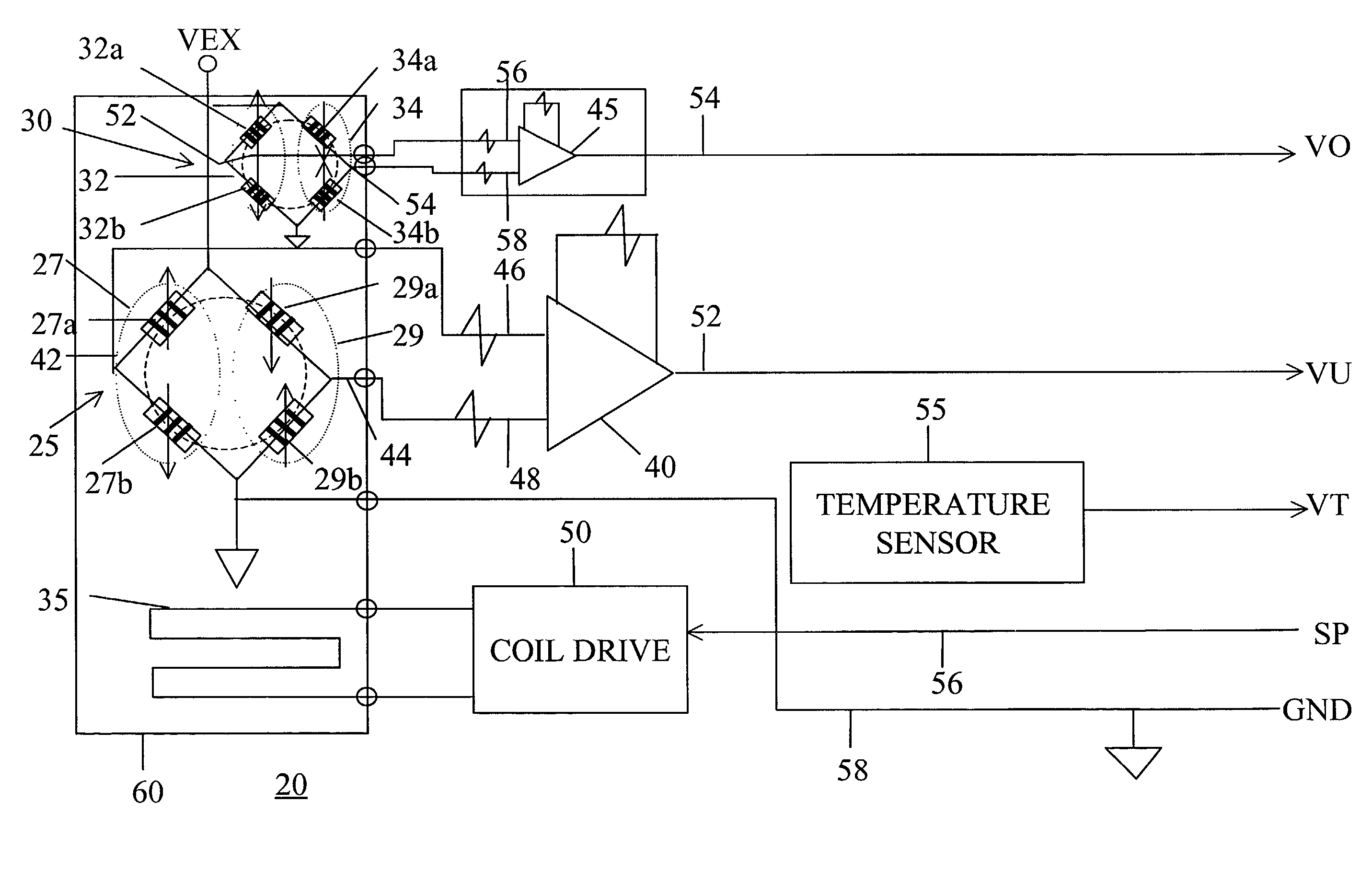
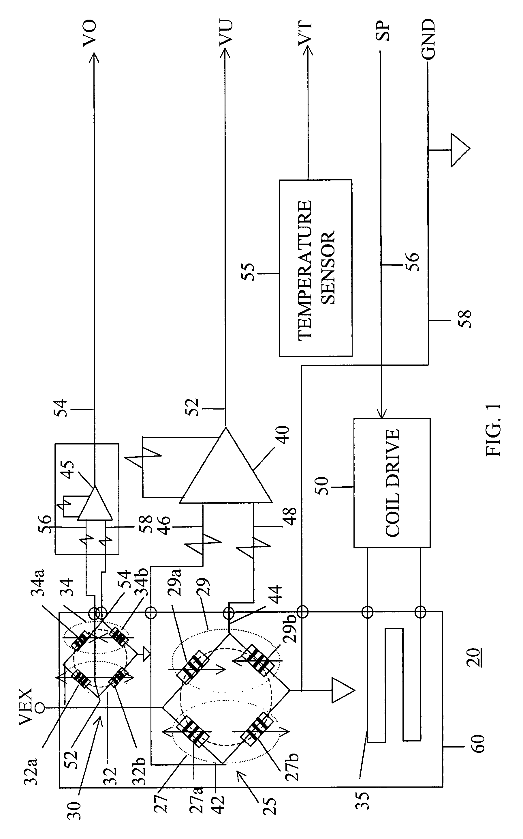
[0048] Referring first to FIG. 1, the remote sensing device according to the invention, generally noted at 20, comprises a first magnetoresistive bridge 25, a second magneto resistive bridge 30, a biasing coil 35, a first differential amplifier 40, a second differential amplifier 45, and a drive circuit 50 for coil 35. A temperature sensor 55 may also be provided as discussed below.

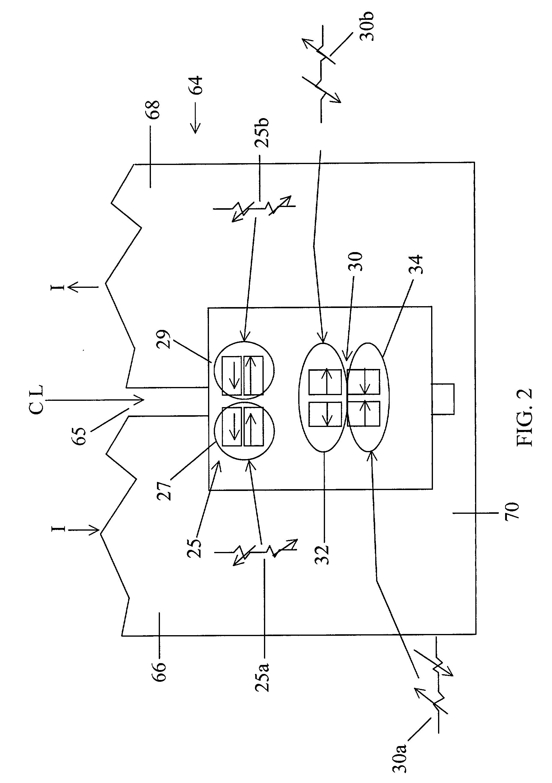
[0049] First MR bridge 25 is comprised of two half bridge sections 27 and 29. Second MR bridge 30 is similarly formed of two half bridge sections 32 and 34. Half bridge sections 27 and 29 are respectively formed of quarter bridge sections or legs 27a and 27b, and 29a and 29b. Similarly, half bridge sections 32 and 34 are respectively formed of quarter bridge sections or legs 32a and 32b, and 34a and 34b.

[0050] The common point between legs 27a and 27b is connected by a signal path 42 to a first input 46 of differential amplifier 40. The common point 44 between legs 29a and 29b is connected by a second sig...


PUM


Abstract

A magnetic field measuring device useful for measuring a magnetic field associated with an electric current, including a bus section connectable into the path of the electric current, a first magnetoresistive (MR) bridge oriented to be sensitive to the magnetic field of a current in the bus section, a second MR bridge oriented to be substantially insensitive to the magnetic field of a current in the bus section, a biasing coil configured and positioned to apply a magnetic field to the first and second MR bridges, whereby the sensitivity of the first MR bridge can be controlled; and a signal processing device responsive to a voltage output of the second MR bridge to control the current through the biasing coil. The device exhibits good rejection of stray magnetic and electric fields, is convenient to use, and can be fabricated in a single chip, with or without associated signal processing and conditioning circuitry, using conventional IC processing techniques.

Description

[0001] 1. Field of the Invention[0002] The present invention relates to magnetoresistive (MR) sensing devices, and more particularly, to MR sensing devices for measuring magnetic fields having improved rejection of stray magnetic fields, and temperature stability, and other improved features. Such devices find utility as current sensors and diagnostic devices in motor controllers, as sensors for powerline communication systems, for position sensing using the fields of permanent magnets to indicate position, and in other applications where information can be derived from time or spatially varying magnetic fields.[0003] 2. Related Art[0004] Conventionally, current flowing in a circuit has been measured using current transformers or Hall Effect sensors or by measuring voltage across a reference element in the circuit. Such current sensors are subject to several disadvantages, especially when used with motor controllers.[0005] For example, current transformers are frequency sensitive, a...

Claims


Application Information

Patent Timeline
IPC IPC(8): G01R33/09
CPCG01R33/09G01R33/096G01R15/205
Inventor GOETZ, JAY
Owner INTERNATIONAL RECTIFIER COEP
Why Eureka
Try Eureka