Process for producing high-nitrogen ultralow -carbon steel

a technology of high-nitrogen ultralow-carbon steel and process, which is applied in the field of process for producing high-nitrogen ultralow-carbon steel, can solve the problems of low nitrogen solubility, slow nitrogen increase rate, and extreme difficulty in obtaining ultra-low-carbon steel, and achieve low carbon content, high productivity, and low cost

Inactive Publication Date: 2003-04-03
JFE STEEL CORP
View PDF3 Cites 7 Cited by
  • Summary
  • Abstract
  • Description
  • Claims
  • Application Information

AI Technical Summary

Benefits of technology

0012] This invention proposes a method of producing, at a reduced cost and with high productivity, a steel for obtaining a steel sheet to be worked which contains nitrogen at high concentration (solid-solute nitrogen) and ultra low carbon content. The steel obtained by the method according to this invention is served particularly for application use in which an aging heat treatment is applied for improving the strength after forming such as press forming and which is suitable as a rolling material for steel sheets having excellent age hardening property.

Problems solved by technology

However, since this method is a treatment in the ladle refining furnace, it is difficult to apply, for example, a vacuum degassing treatment, so that it is extremely difficulty to obtain a ultra low carbon steel.
However, the nitrogen injection method by a nitrogen gas involves a drawback that the nitrogen increasing rate is slow.
Particularly, in the steel material used for steel sheets to be worked, since Cr concentration is low different from stainless steel and the like, the nitrogen solubility is low and it is difficult to attain a processing speed suitable to industrial production.
While the disclosed technique propose an attempt of increasing nitrogen up to an equilibrated nitrogen concentration by increasing the pressure in the vacuum vessel, this also requires a long time to reach the equilibrated nitrogen concentration when the initial nitrogen concentration is low.
Accordingly, when the aimed nitrogen concentration is, for example, 0.0120 mass % or more as described above, it is extremely difficult to attain the aimed value by the injection of the nitrogen gas.
However, like the techniques described previously, nitrogen increasing rate in the injection of nitrogen by the nitrogen gas is slow and it takes a long processing time in ordinary steels, which is not practical.
For example, it results in a problem that the C concentration in the molten steel is increased by C contained in the alloy.
At the same time, the nitrogen-containing alloy with controlled composition is expensive and it is difficult aside from special steels, to adopt such an uneconomical method for steel species as in steel sheets put to ordinary working that require mass production and production at reduced cost.
However, when the denitridation reaction along with the decarburizing treatment in the secondary refining is taken into consideration, this method requires addition of a great amount of nitrogen in total compared with a case of adding nitrogen only in the secondary refining.
Accordingly, in conjunction with the low processing rate for the high nitrogen treatment, only low production efficiency can be expected by the gas in this method.
Further, it has been actually difficult to attain an N content of 0.0120 mass % or more in a ultra low carbon steel at: C.ltoreq.0.005 mass % by any of the methods described above.

Method used


Image

  • Process for producing high-nitrogen ultralow -carbon steel
  • Process for producing high-nitrogen ultralow -carbon steel
  • Process for producing high-nitrogen ultralow -carbon steel

Examples


##ventive example 1

Inventive Example 1

[0083] A primary decarburizing treatment was applied to 250 t of molten iron in a converter furnace to lower the C concentration as far as 0.0300 mass %. In this state, the N concentration was 0.0040 mass % and the Mn concentration was 0.07 mass % in the molten steel. Subsequently, N--Mn alloy (C: 1.5 mass %, Mn: 73 mass %, N: 5 mass %) was added by 5 kg / t into a ladle upon tapping from a converter furnace to increase the N concentration in the molten steel in the ladle to 0.0140 mass %. In this state, the C concentration was increased to 0.0400 mass % and the Mn concentration was increased to 0.40 mass %.

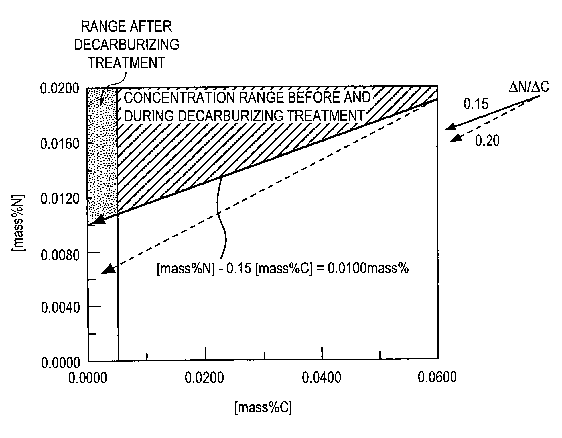
[0084] For decarburization of the molten steel into the ultra low carbon steel, secondary carburization refining was applied by a vacuum decarburizing treatment in an RH type vacuum degassing facility. [mass %N]-0.15 [mass %C] before the secondary decarburization refining was 0.0080 mass % to ensure 0.0060 mass % or more of concentration. During the vacuum decarb...

##ventive example 2

Inventive Example 2

[0090] A primary decarburizing treatment was applied to 250 t of molten iron in a converter furnace to lower the C concentration as far as 0.0300 mass %. In this state, the N concentration was 0.0040 mass % and the Mn concentration was 0.07 mass % in the molten steel. Subsequently, N--Mn alloy (C: 1.5 mass %, Mn: 73 mass %, N: 5 mass %) was added by 5 kg / t into a ladle upon tapping from a converter furnace to increase the N concentration in the molten steel in the ladle to 0.0165 mass %. In this state, the C concentration was increased to 0.0300 mass % and the Mn concentration was increased to 0.40 mass %.

[0091] For decarburization of the molten steel into the ultra low carbon steel, secondary carburization refining was applied by a vacuum decarburizing treatment in an RH type vacuum degassing facility. [mass %N]-0.15 [mass %C] before the secondary decarburization refining was 0.0120 mass % to ensure 0.100 mass % or more of concentration. During the vacuum decarbu...

##ventive example 3

Inventive Example 3

[0096] A primary refining-RH aluminum killed treatment (secondary refining-deoxidation-composition control) were applied under the conditions shown in Tables 2 and 3. The amount of the nitrogen-containing gas charged during the primary refining was as nitrogen gas: 1 Nm.sup.3 / t. Further, in the steels (after refining), the range for the main composition other than those described in the tables comprised P: 0.005 to 0.025 mass % and S: 0.005 to 0.025 mass %, with the balance of inevitable impurities.

2TABLE 2 Inventive Inventive Inventive Inventive Inventive Section Ex. 3-1 Ex. 3-2 Ex. 3-3 Ex. 3-4 Ex. 3-5 Molten iron amount 250 ton 250 ton 250 ton 250 ton 250 ton After N addition gas Type N.sub.2 N.sub.2 no no N.sub.2 primary Composition C 0.03% 0.03% 0.03% 0.03% 0.03% decar- after Mn 0.10% 0.10% 0.10% 0.10% 0.10% burization refining N 0.0100% 0.0140% 0.0040% 0.0040% 0.0100% re-fining On N--Mn alloy addition amount 5 kg / ton -- 6 kg / ton 4 kg / ton 4 kg / ton tapping High...


PUM

PropertyMeasurementUnit
thicknessaaaaaaaaaa
tensile strainsaaaaaaaaaa
pressureaaaaaaaaaa

Abstract

A method of producing a high nitrogen, ultra low carbon steel suitable to rolling material for use in cold rolled steel sheets having excellent age hardening property by an age hardening treatment after forming by working, with no defects in slabs or steel sheets, reliably, at a reduced cost and with a high productivity is proposed. The method for producing a rolling material for use in ultra low carbon steel sheets at: C<=0.0050 mass % comprises; applying primary decarburization refining to molten iron from a blast furnace, then controlling the composition in the molten steel after primary decarburization refining to a range satisfying the following relation: [mass %N]-0.15 [mass %C]>=0.0060, subsequently conducting secondary decarburization refining to a ultra low carbon concentration region while suppressing denitridation using a vacuum degassing facility, then conducting deoxidation by Al and, further, controlling the composition such that [mass %Al].[mass %N]<=0.0004, N: 0.0050 to 0.0250 mass % and, preferably, with the amount of solid solute N being at a predetermined amount or more and then casting the molten steel continuously.

Description

[0001] This invention concerns a method of producing a ultra low carbon steel at high nitrogen concentration, particularly, a ultra low carbon steel at high concentration of solid-solute N. The ultra low carbon steel at high nitrogen concentration can be applied, for example, with rolling to obtain a ultra low carbon steel sheets (thin steel sheets) of high age hardening property. The high nitrogen ultra low carbon steel sheets can be used for portions such as of automobile structural parts, which require structural strength, particularly, strength and / or rigidity upon deformation.[0002] As one of steel sheets suitable, for example, to automobile structural parts, steel sheets which have favorable workability and can be improved for the strength by an aging heat treatment after once being formed (hereinafter referred to as age hardening property) have been proposed. In the steel sheets, the strength can be improved by applying forming such as press forming in a relatively soft state...

Claims


Application Information

Patent Timeline
Patent Type & Authority Applications(United States)
IPC IPC(8): C21C7/04C21C7/068C21C7/10C22C38/00C22C38/04
CPCC21C7/04C21C7/068C22C38/04C22C38/001C22C38/004C21C7/10C21C7/06
Inventor NABESHIMA, SEIJITAKEUCHI, SHUJIOGAWA, HISASHINABESHIMA, YUKIMASUMOTO, YASUYUKI
Owner JFE STEEL CORP
Why Eureka
Try Eureka