Aspiration unit

a technology of aspiration unit and aspiration chamber, which is applied in the field of dental instruments, can solve the problems of large area contaminating the operative field and adjacent areas, buildup of water in the patient's mouth, and aerosol contamination, and achieve the effect of reducing the amount of airborne particles, reducing the time required for patient rinsing, and simple design

Inactive Publication Date: 2003-04-17
VAN HALE GREGORY L
View PDF0 Cites 12 Cited by
  • Summary
  • Abstract
  • Description
  • Claims
  • Application Information

AI Technical Summary

Benefits of technology

0011] Another object of the invention is to provide an apparatus as described which dramatically decreases the amount of airborne particles, aerosols and other contaminates which may be generated during the scaling procedure.
0012] Another object of the invention is to provide an apparatus of the aforementioned character that significantly reduces the time required for patient rinsing. Another object of the invention is to provide an aerosol unit of the character described in the preceding paragraph, which is of simple design for ease of manufacture and one, which can be inexpensively produced, in large volume.
0013] Still another object of the invention is to provide an aspiration unit having a lightweight, plastic body portion which is disposable or reusable and can be removably attached proximate one end to a source of vacuum and is provided proximate its other with a suction scoop of novel design. More particularly, one form of the suction scoop includes a plurality of downwardly extending, flexible bristles that enhance the vacuum proximate the tip and efficiently captures the cooling water and the debris generated during the scaling operation.
0014] Another object of the invention is to provide finger operated valve means for controlling the degree of vacuum created within said interior space of said elongated outer body.

Problems solved by technology

During operation of the conventional prior art ultrasonic scalers, substantial aerosol contamination results.
More particularly, during the scaling procedure, the prior art devices typically generate a substantial aerosol spray of blood, saliva, tissue, calculus and other particulate matter, which can contaminate large areas of the operative field and adjacent areas.
These devices tend to cause a buildup of water in the patient's mouth, which must be periodically removed using conventional suction devices.
These suction devices are generally unwieldy and must be operated by the dental assistant as the dentist performs the scaling procedure.
However, these devices have not received wide acceptance in the field.

Method used


Image

  • Aspiration unit
  • Aspiration unit
  • Aspiration unit

Examples


Embodiment Construction

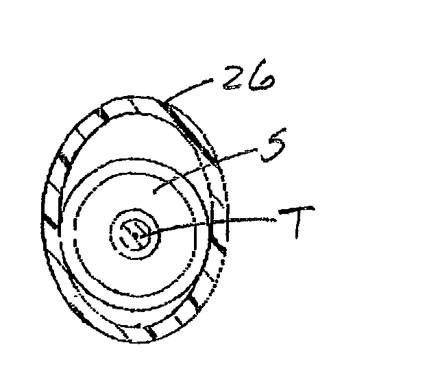
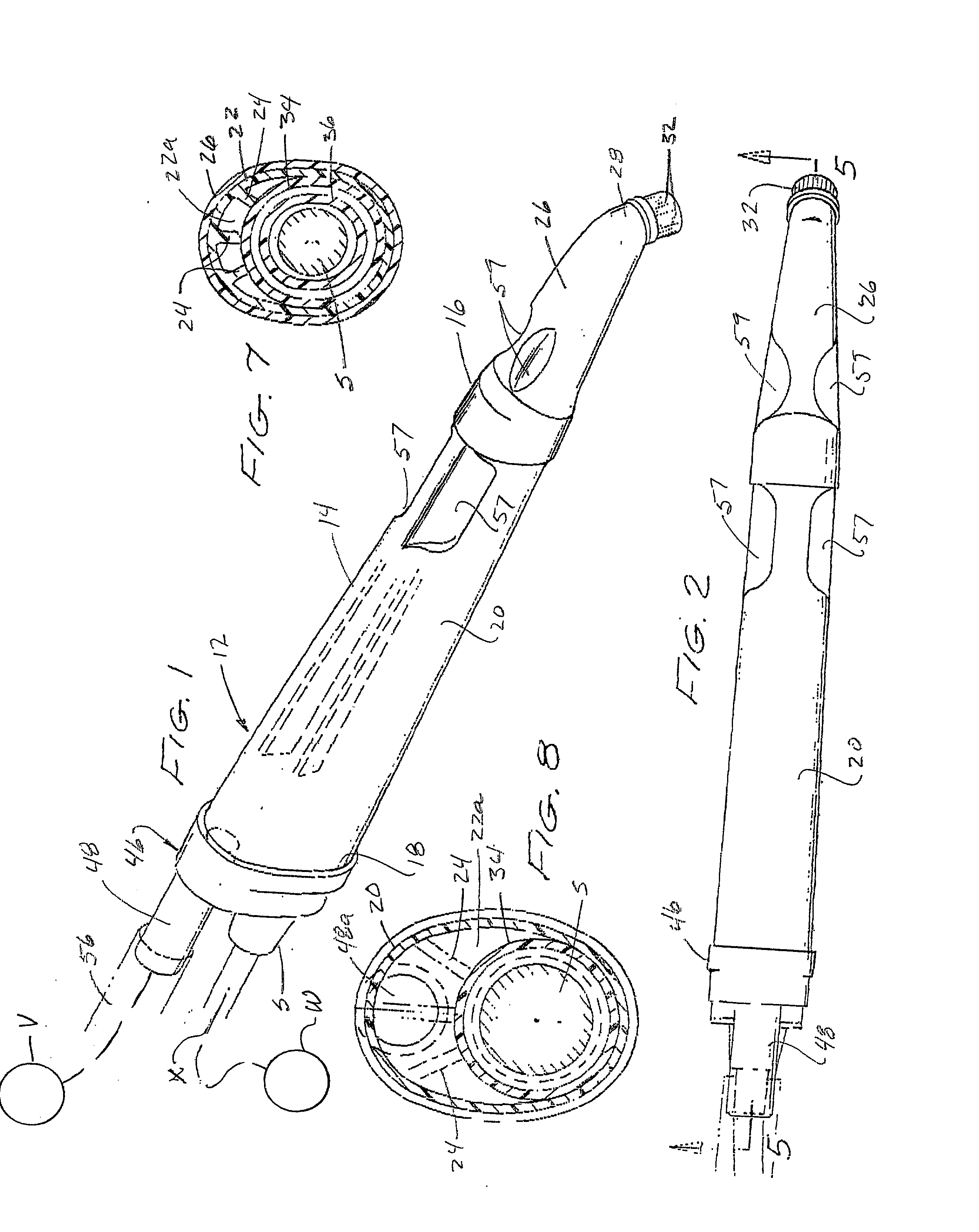
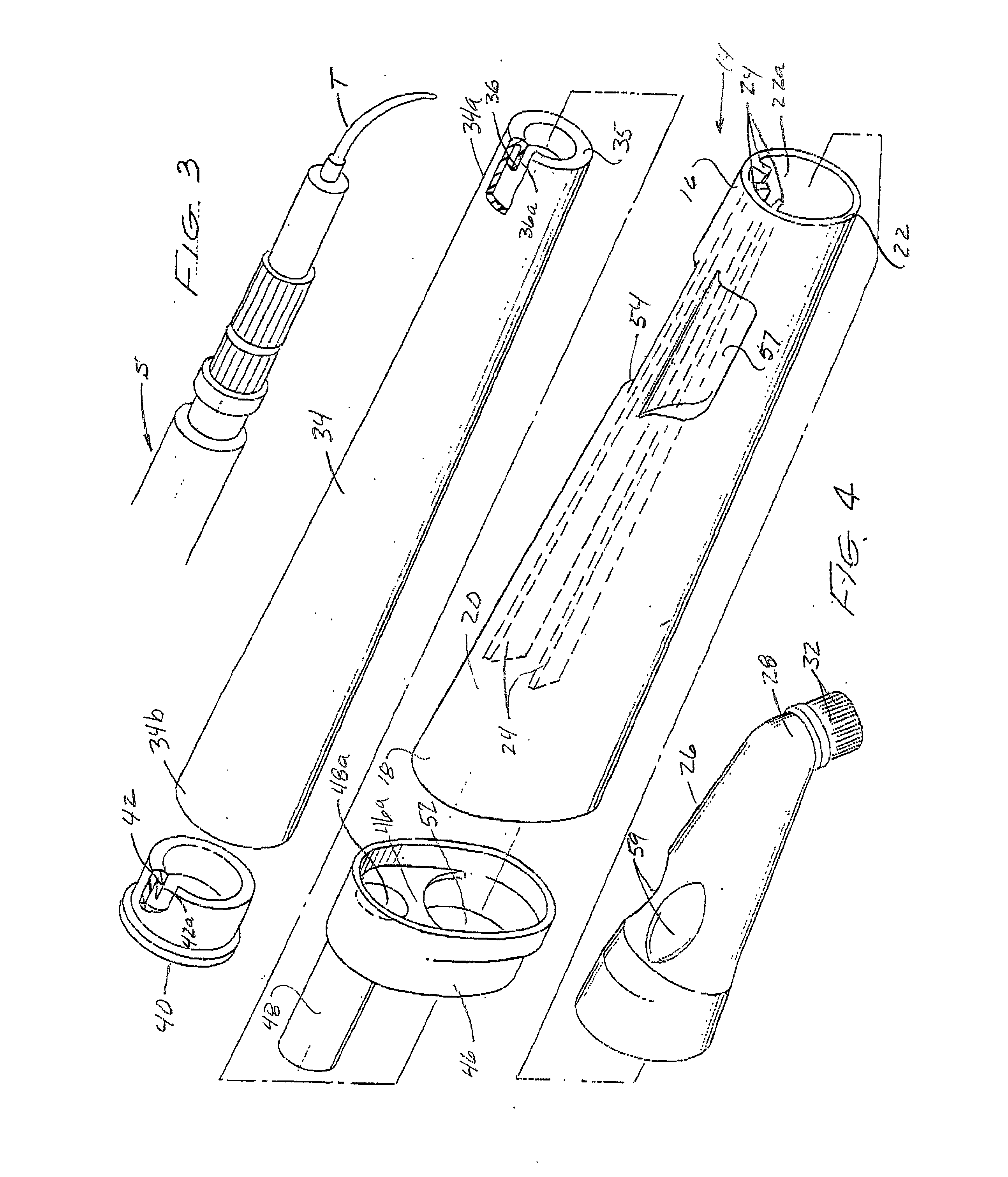
[0030] Referring to the drawings and particularly to FIGS. 1 and 2, one form of the aspiration unit of the present invention is there shown operably interconnected with a dental instrument such as a scaler "S" of a conventional design. The assembled unit, which is generally designated by the numeral 12, comprises an elongated, specifically configured, hand held assemblage 14 having first distal and second proximal end portions 16 and 18 respectively. As is best seen by referring to FIGS. 4 and 5, assemblage 14 includes an elongated, tapered outer body 20 having a circumscribing wall 22. Attached to and extending radially inwardly from wall 22 are three spaced apart standoffs 24, the purpose of which will presently be described.

[0031] Wall 22 progressively increases in diameter from the first end portion 16 to the second end portion 18 so as to define a longitudinally extending interior space 22a (FIGS. 4 and 5). Provided proximate the first or distal end portion 16 of body 20 is an ...


PUM


Abstract

A readily disposable aspiration unit that can be connected to various dental instruments of conventional design including ultrasonic scalers. The aspiration unit includes a novel suction means for automatically carrying away from the operative field cooling water and debris generated during the performance of the scaling procedure. The unit further includes a tip-encompassing shroud that uniquely functions as a suction scoop for automatically capturing aerosols in the operative field including aerosols containing saliva, blood, tissue, calculus and like adherent deposits, which are generated during the scaling procedure.

Description

FIELD OF THE INVENTION[0001] The present invention relates generally to dental instruments. More particularly, the invention concerns an improved, disposable aspirating unit usable with dental instruments of conventional construction for cutting, drilling, aspirating and scaling operations. The aspirating unit has at its distal end a vacuum scoop that circumscribes the scaler tip and expeditiously carries away particulate matter generated during operation of the scaler as well as controlling aerosols.DISCUSSION OF THE INVENTION[0002] A number of different types of ultrasonic scalers have been suggested in the past. Typically such devices include a curved tip for supplying high frequency vibrations that effectively remove adherent deposits from the teeth and bits of inflamed tissue from the walls of the gingival crevice. Most of the prior ultrasonic scalers include an electrically operated hand piece and one or more autoclavable tips that can be removably connected to the hand piece....

Claims


Application Information

Patent Timeline
Patent Type & Authority Applications(United States)
IPC IPC(8): A61C1/08A61C17/06
CPCA61C17/043A61C1/08A61C17/08
Inventor VAN HALE, GREGORY L.
Owner VAN HALE GREGORY L
Why Eureka
Try Eureka