
Device for the separation of gas and liquid/solid particles in a mixture of gas and fluid/solid particles flowing in a line and method for the separation thereof

Inactive Publication Date: 2003-04-24
ROBERT BOSCH GMBH
View PDF13 Cites 35 Cited by
  • Summary
  • Abstract
  • Description
  • Claims
  • Application Information

AI Technical Summary

Benefits of technology

[0007] In contrast, the device and method according to the present invention having the characterizing features of claim 1 and 13, respectively, has the advantage that liquid and / or solid particles may be separated from a flowing gas / liquid / solid particle mixture in a simple manner.[0008] The measures cited in the dependent claims make advantageous refinements and improvements of the device cited in claim 1 and the method cited in claim 13, respectively, possible.[0009] It is advantageous if the valve is a spring valve since this is a very simple and cost-effective valve.[0010] It is additionally advantageous if the valve is situated in the area of an inlet opening of the line into the channel because as a result, the separation area of the valve may be situated on the line.[0011] It is advantageous in particular if the valve opens only when the pressure ratio or the pressure difference between an upstream area and a downstream area of the line is correspondingly great because this prevents contamination from spreading in the downstream area of the line.[0012] It is advantageous to design the line in such a way that the medium flowing in the line is deflected by approximately 180.degree. at least twice, as a result of which the contaminants, in particular oil or liquids, form a wall film or large drops on an inside wall of the line and thus do not so easily continue to flow along with the flowing medium downstream of a deflecting element.[0013] Solid particles also accumulate on the inside wall and form a mixture with the liquid in the wall film, as a result of which the solid particles with the liquid are separated from the flowing medium.[0014] The flowing medium may be deflected in an advantageous manner in that the deflecting element is in the shape of a plate and is larger in cross-section than a ring having a smaller cross-section than the line in the area of the deflecting element.[0015] The deflecting element may advantageously be a valve plate of a valve.[0016] The line may be connected in an advantageous manner with a channel in which a measuring element is situated because the measuring element is protected in this manner against contamination even if undesirable contaminants flow from the line into the channel.[0017] It is advantageous to design the line as a Laval nozzle in the area of an inlet opening into the channel since this accelerates the flow in the channel at that point and foreign particles are more strongly led away from the measuring element.[0018] Moreover, it is advantageous to arrange the line in the area of the inlet opening obliquely to the channel since in this manner the medium is specifically guided out of the channel away from the measuring element.

Problems solved by technology

In process engineering in general and in automotive engineering, e.g., rainwater in the intake connection piece of the air filter housing, and other technical fields of application, the problem frequently occurs that liquids are mixed with gases or vapors and they must be separated.
Depending on the application, the problems caused by liquids are corrosion, malfunctions and possibly the destruction of equipment.
During the operation of a measuring device having a measuring element to determine parameters of a medium to be measured, a test medium flowing in a channel, for example, an intake connection piece of an internal combustion engine, it may occur that, against the main direction of flow of the test medium, e.g., air, oil droplets or oil vapor from a line such as, for example, a crankcase vent line, or other foreign particles flow into the channel and the measuring element is contaminated by the oil or the foreign particles.
As a result, the measuring characteristics of the measuring element are noticeably worsened.

Method used


Image

  • Device for the separation of gas and liquid/solid particles in a mixture of gas and fluid/solid particles flowing in a line and method for the separation thereof
  • Device for the separation of gas and liquid/solid particles in a mixture of gas and fluid/solid particles flowing in a line and method for the separation thereof
  • Device for the separation of gas and liquid/solid particles in a mixture of gas and fluid/solid particles flowing in a line and method for the separation thereof

Examples


Embodiment Construction

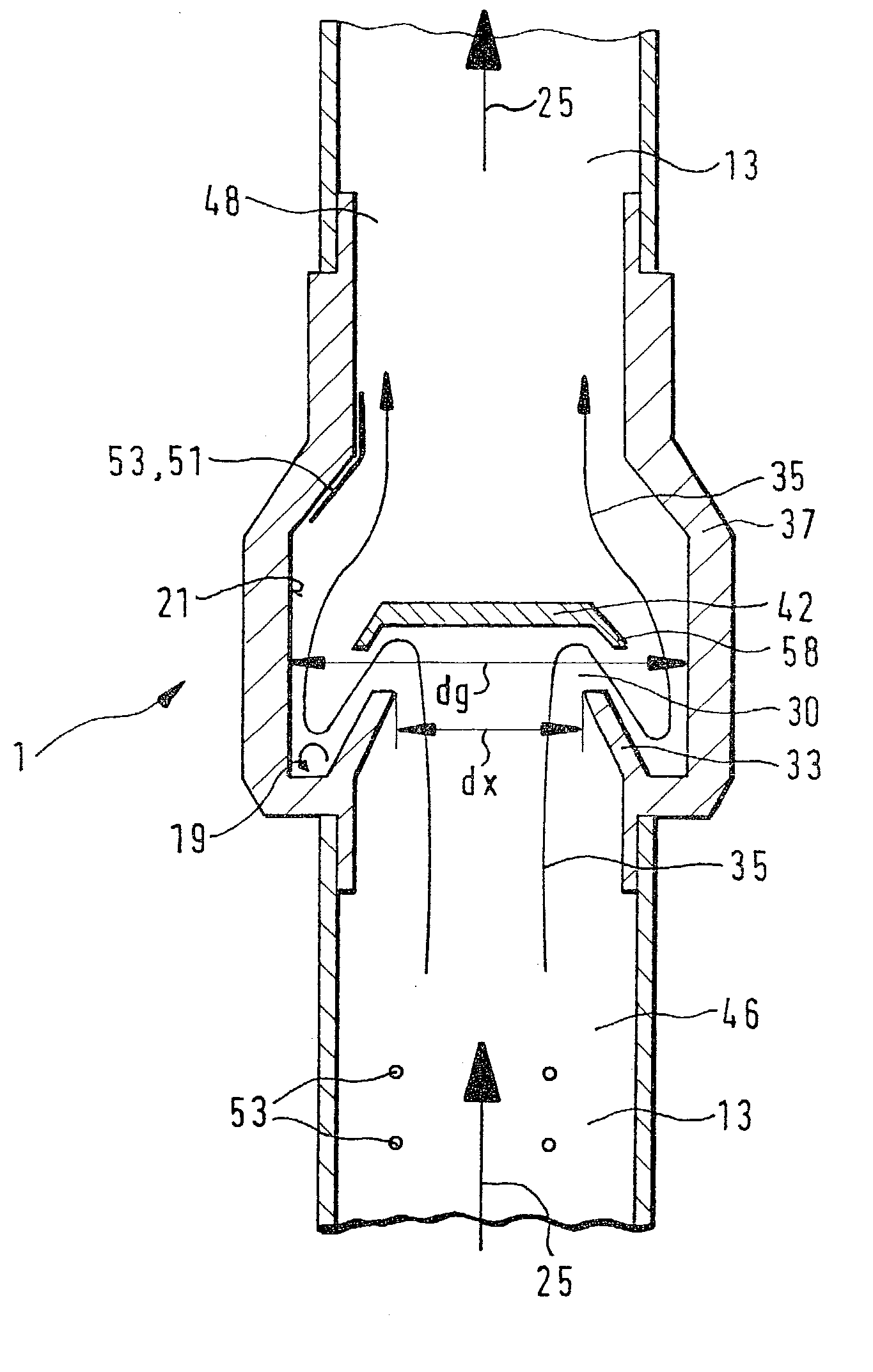
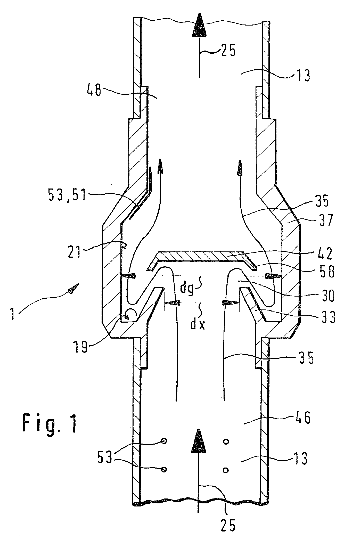
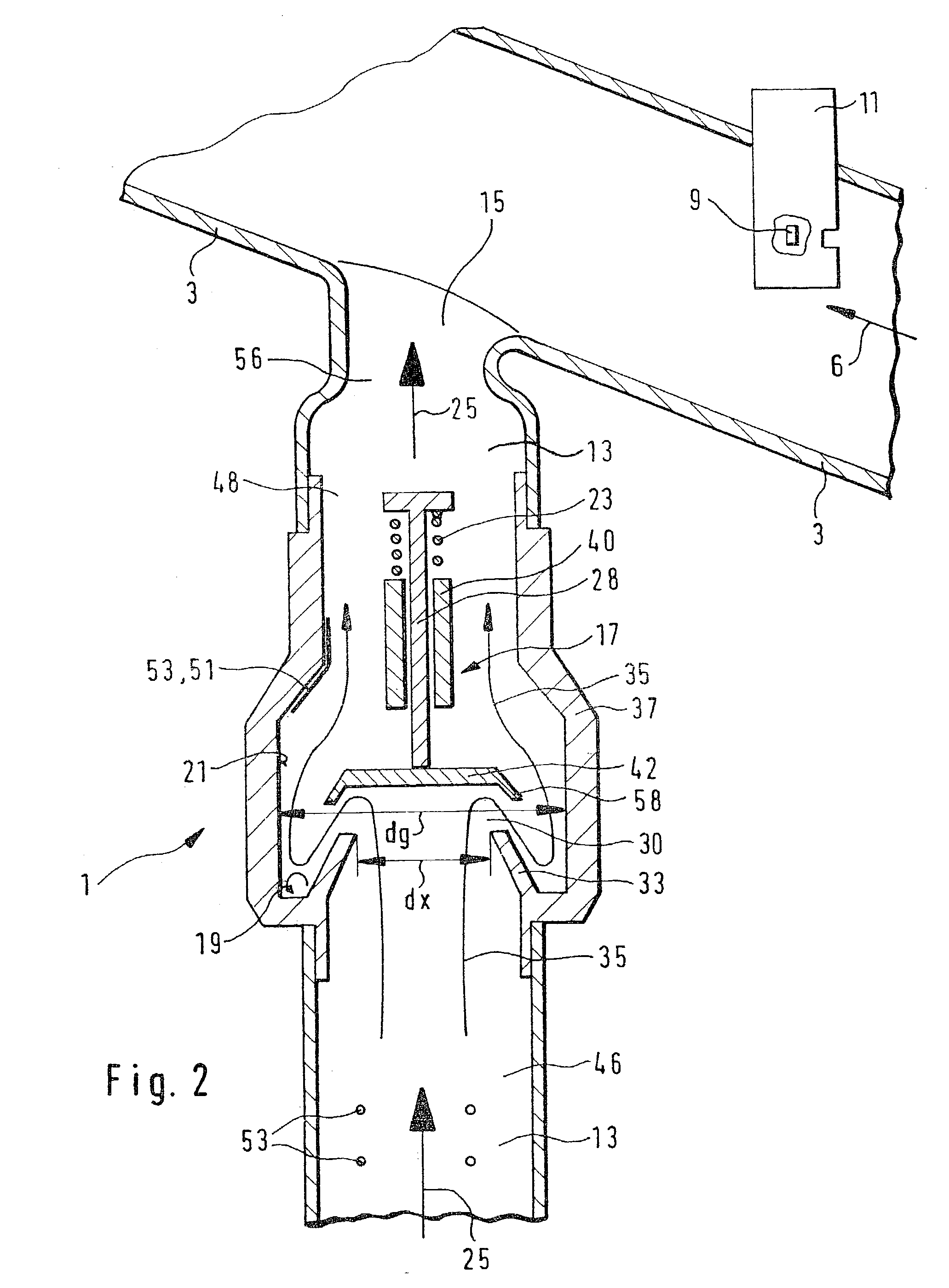
[0022] FIG. 1 shows a device 1 for separating gas and liquid / solid particles from a medium, a gas / liquid / solid particle mixture flowing in a line 13. The medium flows in line 13 in the direction of a line flow direction 25. Undesirable components, for example, oil vapors or oil particles from a crankcase housing may flow in line 13. In many cases, it is desirable to separate liquid and solid particles from the gas so that the liquid and / or the solid particles do not reach devices present in the line.

[0023] To achieve this, a deflecting element 42 is situated in line 13. The medium flowing in line 13 is, for example, deflected at least twice by approximately 180.degree.. This produces separating vortexes 19 which cause oil particles 53 or the oil vapor in the flowing medium to reach inside wall 21 of line 13 and form a wall film 51 there. It is possible to speak of a centrifuging of the oil / gas mixture.

[0024] Any solid particles present such as, for example, dust particles are also f...


PUM

PropertyMeasurementUnit
Angleaaaaaaaaaa
Shapeaaaaaaaaaa
Areaaaaaaaaaaa

Abstract

According to the related art, a separation of gas and liquid-solid particles from a medium flowing in a line is only known in a device having two outlet openings. In a device according to the invention (1) having a line (13) in which the medium flows, a deflecting element (42) is situated in the line (13), which generates separating vortexes (19) in the medium and thus separates gas from liquid / solid particles.

Description

BACKGROUND INFORMATION[0001] The present invention is directed to a device for separating gas and liquid / solid particles from a gas / liquid / solid particle mixture flowing in a line and a method for separating the same according to the definition of the species in claim 1 and 13, respectively.[0002] A device for separating gas and liquid from a gas / liquid mixture flowing in a line and a method of the separation of the same are known from U.S. Pat. No. 5,507,858. The device, however, necessarily has two outlet openings.[0003] In process engineering in general and in automotive engineering, e.g., rainwater in the intake connection piece of the air filter housing, and other technical fields of application, the problem frequently occurs that liquids are mixed with gases or vapors and they must be separated. Depending on the application, the problems caused by liquids are corrosion, malfunctions and possibly the destruction of equipment.[0004] During the operation of a measuring device hav...

Claims


Application Information

Patent Timeline
IPC IPC(8): F01M13/04B01D45/06B01D45/08F02M35/022
CPCB01D45/06B01D45/08Y10S55/19F02M35/022F01M2013/0433
Inventor LENZING, THOMAS
Owner ROBERT BOSCH GMBH
Learn More