Apparatus and method for dispensing high-viscosity liquid

a technology of liquid and apparatus, applied in the direction of liquid transferring device, liquid handling, instruments, etc., can solve the problems of premature wear of pump and valve, ineffective use of limited cross-sectional area of separate tubing configuration, and inability to effectively use the limited cross-sectional area of the tubing

Inactive Publication Date: 2003-04-24
TEXAS INSTR INC +1
View PDF13 Cites 38 Cited by
  • Summary
  • Abstract
  • Description
  • Claims
  • Application Information

AI Technical Summary

Problems solved by technology

Therefore, when the output liquid volume is substantially equal to the re-circulated liquid volume (as usually occurs when purging gas out of the dispensing lines), such difference in cross-sectional flow areas of the output and return flow paths causes an imbalance of discharge pressures in the dispensing line and in the recirculating line.
This imbalance unduly burdens the dispensing pump and the dispensing / recirculating valve and causes the pump and the valve to wear out prematurely.
Such separate tubing configuration does not effectively use the limited cross-sectional area of the opening of the fluid storage and dispensing vessel.
However, such design leaves a free space between the end of the return flow path and the liquid surface within the fluid vessel, and the re-circulated liquid therefore drips in a free-fall manner from the return flow path into the fluid vessel, causing liquid turbulence and deleterious formation of air bubbles in the fluid vessel.

Method used


Image

  • Apparatus and method for dispensing high-viscosity liquid
  • Apparatus and method for dispensing high-viscosity liquid
  • Apparatus and method for dispensing high-viscosity liquid

Examples


Embodiment Construction

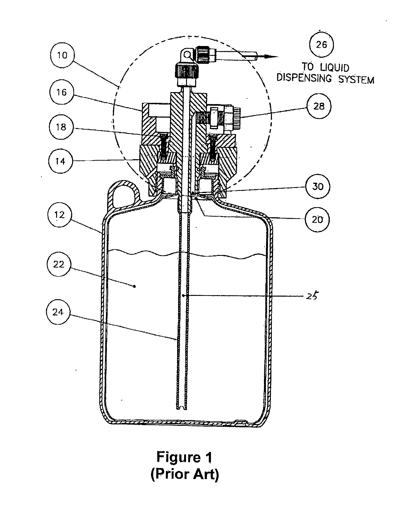
[0043] FIG. 1 ("Prior Art") shows a conventional recirculating probe 10 coupled to opening 20 of a fluid storage and dispensing vessel 12, by a lower connector 14 and an upper connector 16. The lower connector 14 and the upper connector 16 are fastened together by a screw-type fastener 18. The recirculating probe 10 comprises a dip tube 24 that defines an output flow path 25. The upper end of the dip tube 24 is connected with an output port, for flowing a high-viscosity liquid 22 stored by the fluid storage and dispensing vessel 12 through to a liquid dispensing system 26. In order to maintain a continuous flow of the liquid 22 and to prevent gel slug formation within the dispensing lines, the diameter of the dip tube 24 is relatively large (e.g., on the order of 0.375 inch), and the liquid 22 is flowed at a relatively high flow rate. At least a majority percentage of the liquid 22 dispensed to the liquid dispensing system 26 is re-circulated back into the fluid storage and dispensi...


PUM


Abstract

The present invention relates to apparatus and method for re-circulating high viscosity liquids. The apparatus comprises a recirculating probe coupled to a fluid storage and dispensing vessel by a connector, and the recirculating probe comprises: (a) a dip tube defining an output flow path; (b) an output port; (c) a recirculating port; and (d) a return flow path. The output flow path and the return flow path preferably have substantially equal cross-sectional areas, which reduce or eliminate the unbalance between the discharge pressure in the output line and that in the re-circulation line, and prevent premature wearing-out of the dispensing/recirculating pump. The output flow path and the return flow path can also be concentric to each other, which not only maximizes the effective flow area for both output and return flow paths within the limited cross-sectional area of the opening of the fluid vessel, but also avoids liquid turbulence and/or formation of air bubbles caused by free-fall drip introduction of the re-circulated liquid that is commonly observed in conventional recirculating probe designs.

Description

[0001] 1. Field of Invention[0002] The present invention generally relates to apparatus and method for dispensing a process liquid characterized by a high viscosity and a short shelf life.[0003] 2. Related Art[0004] Semiconductor manufacturing processes frequently employ process liquids of high viscosity, such as polyimides (typically having a viscosity of 250-35,000 centipoises), which exhibit a good combination of thermal stability, mechanical toughness and chemical resistance and can be used as protective overcoats, interlayer dielectrics, or passivation layers in microelectronic applications. Due to their high viscosity, these process liquids are usually dispensed from pressurized storage and dispensing vessels, by special dispensing pumps in conjunction with large diameter tubing (e.g., 0.375 inch diameter).[0005] A recirculation loop downstream of the dispensing pump is usually provided to keep the high viscosity process liquid in continuous fluidic motion at a desired flow ra...

Claims


Application Information

Patent Timeline
Patent Type & Authority Applications(United States)
IPC IPC(8): B67D7/02
CPCB67D1/0054B67D7/0255B67D7/0261Y10T137/85954
Inventor PRIEBE, RYANO'DOUGHERTY, KEVIN T.CHEESEBROW, NICHOLAS
Owner TEXAS INSTR INC
Why Eureka
Try Eureka