High-carbon steel wire rod with superior drawability and method for production thereof
a high-carbon steel, wire rod technology, applied in the direction of furnaces, heat treatment equipment, manufacturing tools, etc., can solve the problems of affecting productivity, impede productivity, and the above-mentioned first technology does not provide sufficient breakage resistance as well as good drawability, so as to prolong the life, improve the drawability, and improve the effect of breakage resistan
- Summary
- Abstract
- Description
- Claims
- Application Information
AI Technical Summary
Benefits of technology
Problems solved by technology
Method used
Image
Examples
example b
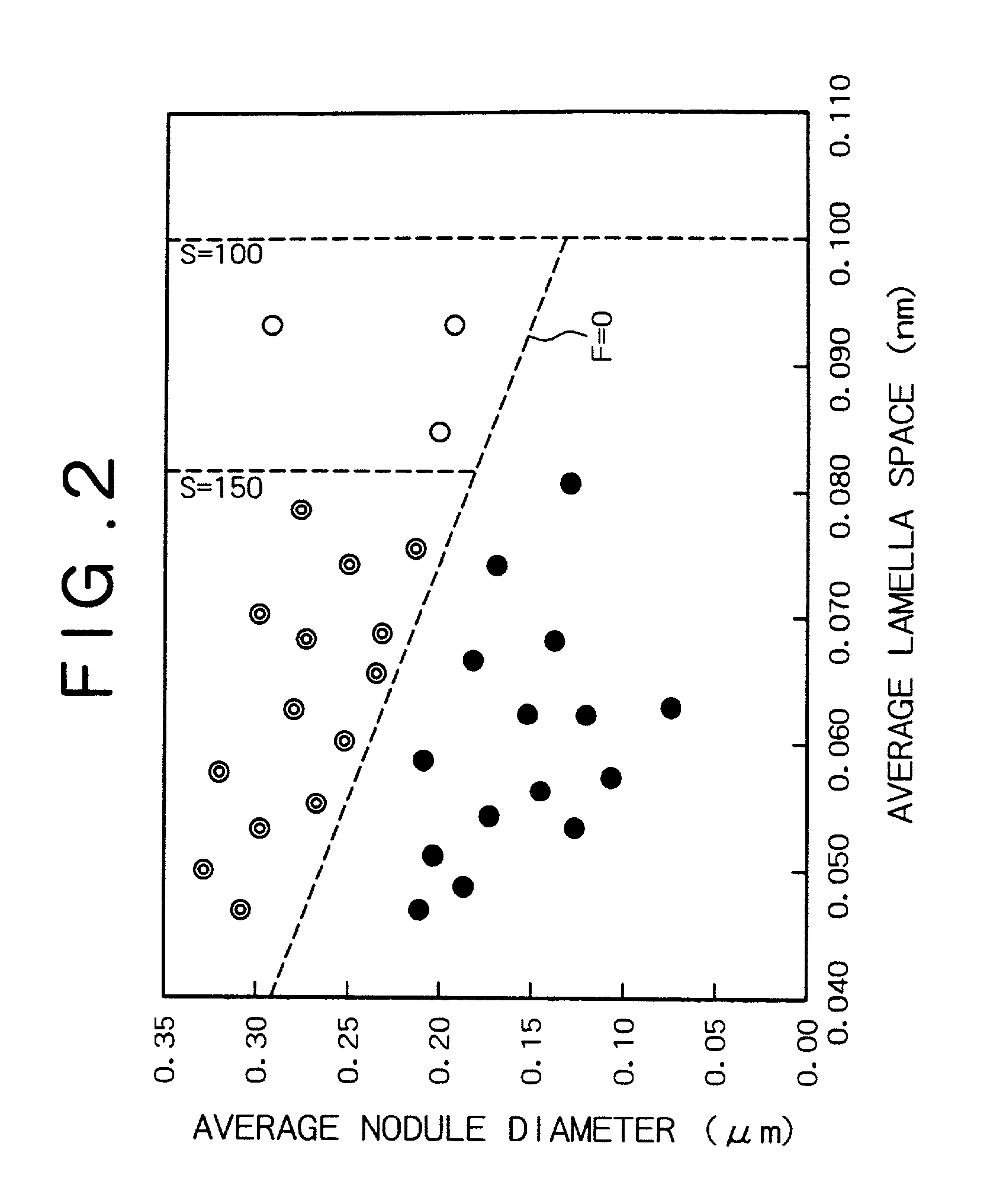
[0079] Steel sample varying in composition as shown in Table 2 were prepared. Each steel was made into hot-rolled wire rods, 5.5 mm in diameter, having the pearlite structure, in the same way as in Example A. The resulting wire rod samples were examined for tensile strength, pearlite area ratio, average lamella space, average nodule diameter, and drawability. The samples containing aluminum were additionally examined for drawability at a higher speed (800 m / min). The results are shown in Tables 3 and 4.
2TABLE 2 Sample Chemical composition (mass %, remainder: substantially Fe) No. C Si Mn P S N Others 1 0.822 0.198 0.512 0.008 0.009 0.0031 2 0.695 0.221 0.712 0.007 0.008 0.0035 3 0.905 0.212 0.558 0.008 0.007 0.041 4 0.819 0.802 0.491 0.005 0.006 0.0029 5 0.820 1.310 0.551 0.008 0.007 0.0038 6 0.809 0.202 0.803 0.005 0.007 0.0039 7 0.818 0.209 0.489 0.011 0.009 0.0041 Nb: 0.026 8 0.809 0.21 0.505 0.007 0.009 0.0042 V: 0.15 9 0.826 0.172 0.489 0.005 0.006 0.0040 Nb: 0.024, V: 0.06 21*...
example c
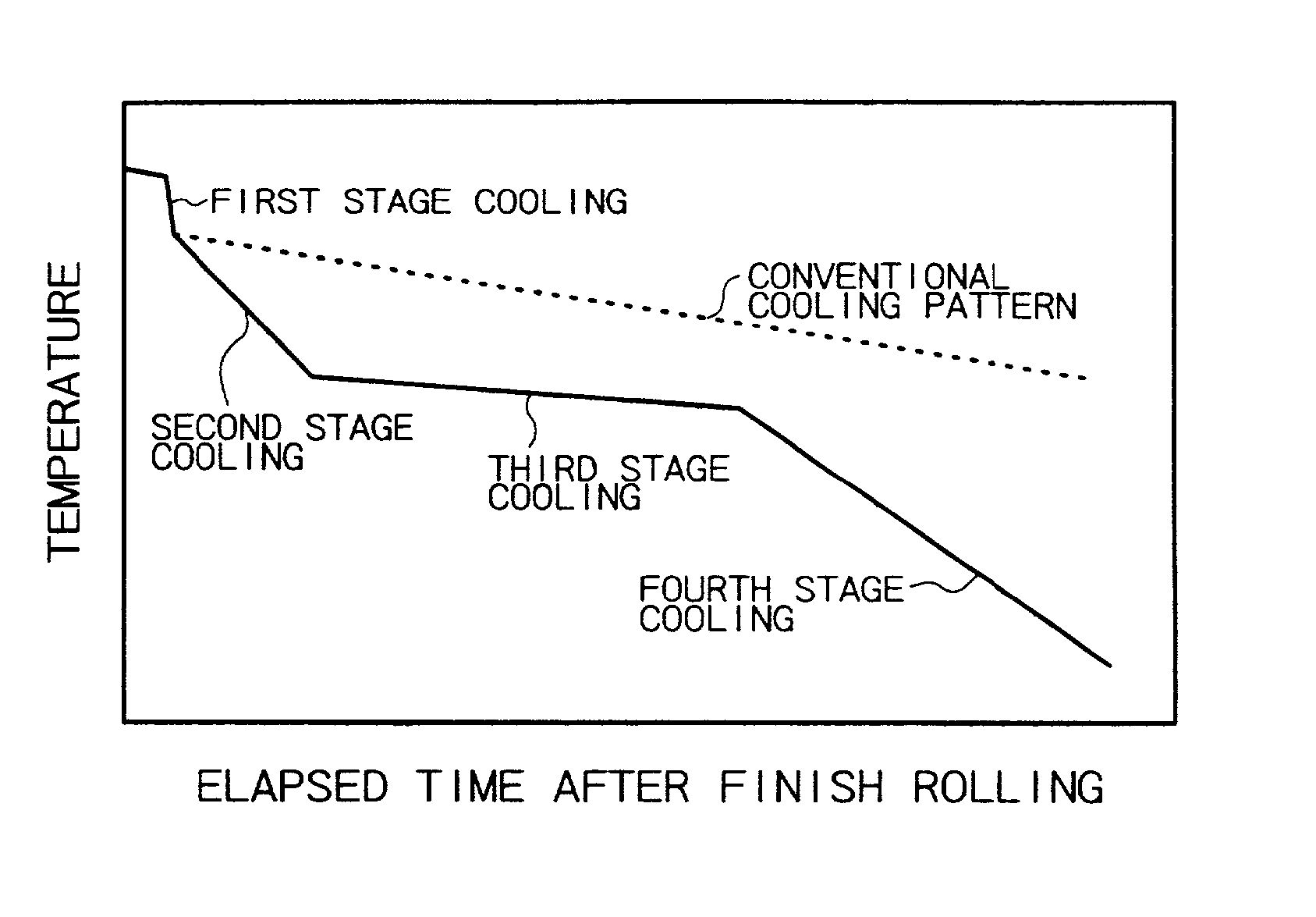
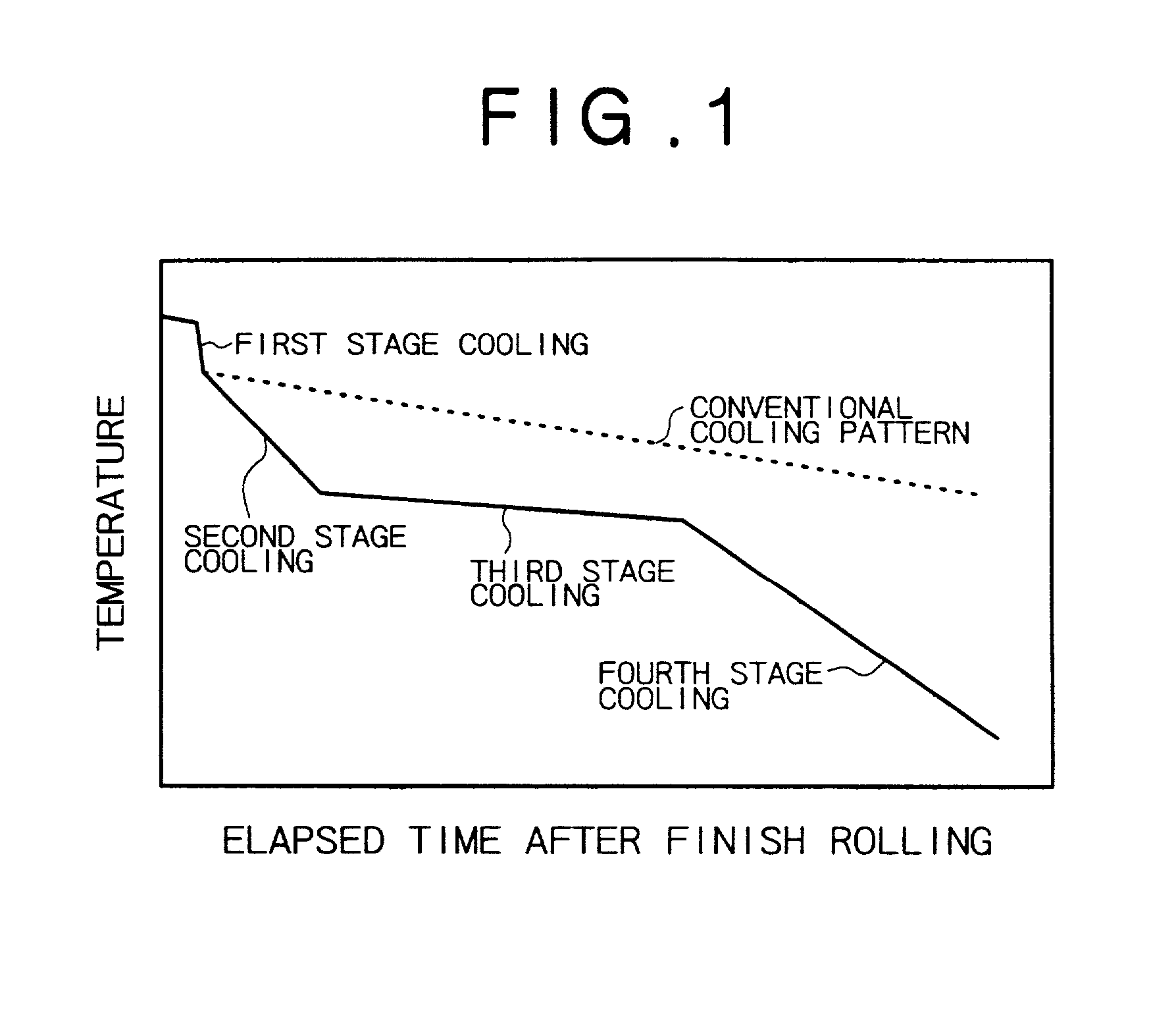
[0083] A high-carbon steel having the composition (shown below) specified in the present invention was prepared. The steel was made into a billet by continuous casting. The billet was made into a wire rod, 5.5 mm in diameter, by hot-rolling at a finish temperature as shown in Table 5. Immediately after hot-rolling, the wire rod was cooled according to the cooling curve shown in FIG. 1 and the cooling scheme (cooling rate, final cooling temperature, and cooling time) shown in Table 5. The first stage cooling was by water-quenching, the second and fourth stage cooling was by air-blast quenching, and the third stage cooling was by natural cooling without air blast.
[0084] Steel composition (mass%, remainder Fe)
[0085] C: 0.816%, Si: 0.15%, Mn: 0.46%, P: 0.007%, S: 0.005%, and N: 0.0025%
[0086] The resulting wire rod samples were examined for tensile strength, pearlite area ratio, average lamella space, average nodule diameter, and drawability. The results are shown in Table 6.
5 TABLE 5 Fi...
example d
[0090] A high-carbon steel having the composition (shown below) specified in the present invention was prepared. The steel was made into a billet by continuous casting as in Example C. The billet was made into a wire rod, 5.5 mm in diameter, by hot-rolling at a finish temperature as shown in Table 7. The wire rod was drawn in the same way as in Example C except that the cooling rate was varied, and the effect of cooling rate on the product properties was examined. The results are shown in Tables 8-1 and 8-2.
[0091] Steel composition (mass %, remainder: Fe) C: 0.790%, Si: 0.18%, Mn: 0.38%, P: 0.006%, S: 0.009%, N: 0.0035%, and Al: 0.018%.
7 TABLE 7 Finish First stage cooling Second stage cooling Third stage cooling Fourth stage cooling temperature Final Final Final Final Sample of hot Cooling temperature Cooling temperature Cooling temperature Cooling temperature No. rolling (.degree. C.) rate (.degree. C / s) (.degree. C.) rate (.degree. C. / s) (.degree. C.) rate (.degree. C. / s) (.degree...
PUM
| Property | Measurement | Unit |
|---|---|---|
| diameter | aaaaa | aaaaa |
| diameter | aaaaa | aaaaa |
| temperature | aaaaa | aaaaa |
Abstract
Description
Claims
Application Information
 - R&D
- Intellectual Property
- Life Sciences
- Materials
- Tech Scout
- Unparalleled Data Quality
- Higher Quality Content
- 60% Fewer Hallucinations
Browse by: Latest US Patents, China's latest patents, Technical Efficacy Thesaurus, Application Domain, Technology Topic, Popular Technical Reports.
© 2025 PatSnap. All rights reserved.Legal|Privacy policy|Modern Slavery Act Transparency Statement|Sitemap|About US| Contact US: help@patsnap.com


