Goniometer-based body-tracking device and method

a goniometer and body technology, applied in the direction of instruments, applications, person identification, etc., can solve the problems of lag time rendering the position data non-real time, limited work space, and both require direct line of sigh

Inactive Publication Date: 2003-05-01
IMMERSION CORPORATION
View PDF28 Cites 184 Cited by
  • Summary
  • Abstract
  • Description
  • Claims
  • Application Information

AI Technical Summary

Problems solved by technology

Such E / M tracking systems are sensitive to the presence of metal in the close surroundings and, in addition, have a workspace limited by the requirement that the receiver(s) remain within several feet of their corresponding transmitter.
Another disadvantage of E / M technology is that it typically includes lag time which renders the position data non-real time.
US and IR technologies have the disadvantage, however, that they both require direct line of sight.
Thus, when one hand passes in front of the other, the position signal can be lost.
Additionally, US technology, in particular, is very sensitive to ambient acoustic noise.
Such optical tracking systems have an inherent workspace limitation that comes from the need to use cameras, namely that the user of the system is limited to the relatively small workspace that is both visible to the cameras and in focus.
Tracking problems occur when markers become occluded, since data cannot be recorded.
In addition, such a system requires a non-trivial amount of post-processing of the data; while it is expected that computing power and cost efficiency will continue to increase, optical systems still do not deliver on-the-spot, "real-time" data.
Also for example, such a system does not help at all with the problem of measuring the motion of living humans and is of little utility in biomechanics and ergonomic applications.
The guides also limit the range of motion of the neighboring joints.
The guides for adjacent links are typically designed to come into contact at a pre-determined joint angle, thus limiting joint range by preventing the joint from bending further.

Method used


Image

  • Goniometer-based body-tracking device and method
  • Goniometer-based body-tracking device and method
  • Goniometer-based body-tracking device and method

Examples


Embodiment Construction

[0081] The inventive structure and method are now described in the context of specific exemplary embodiments. For convenience, but not by way of limitation, the description is partitioned into a system overview, a description of the kinematic foundation of the mechanical components and assemblies, and a description of elements, components, sensors, assemblies, and the like corresponding to the attached figures.

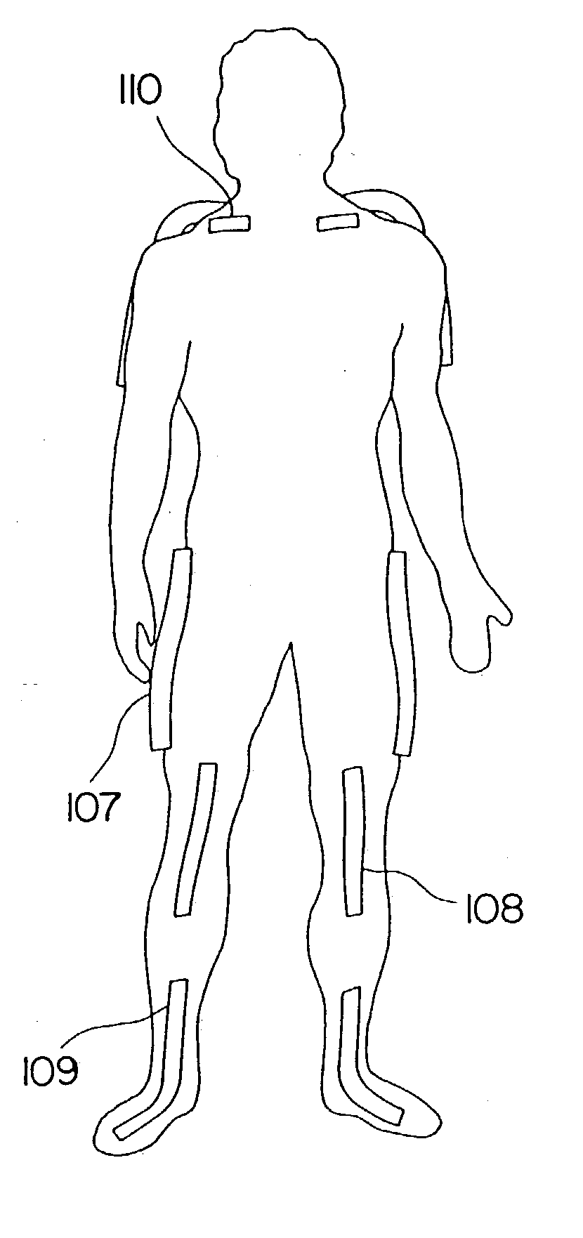
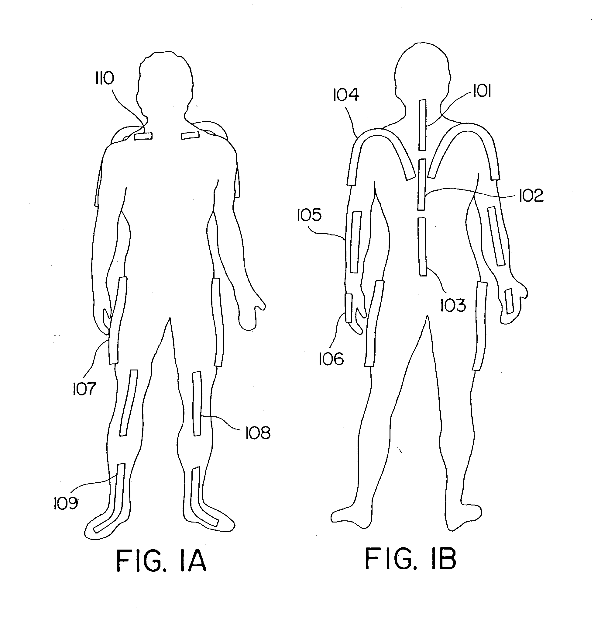
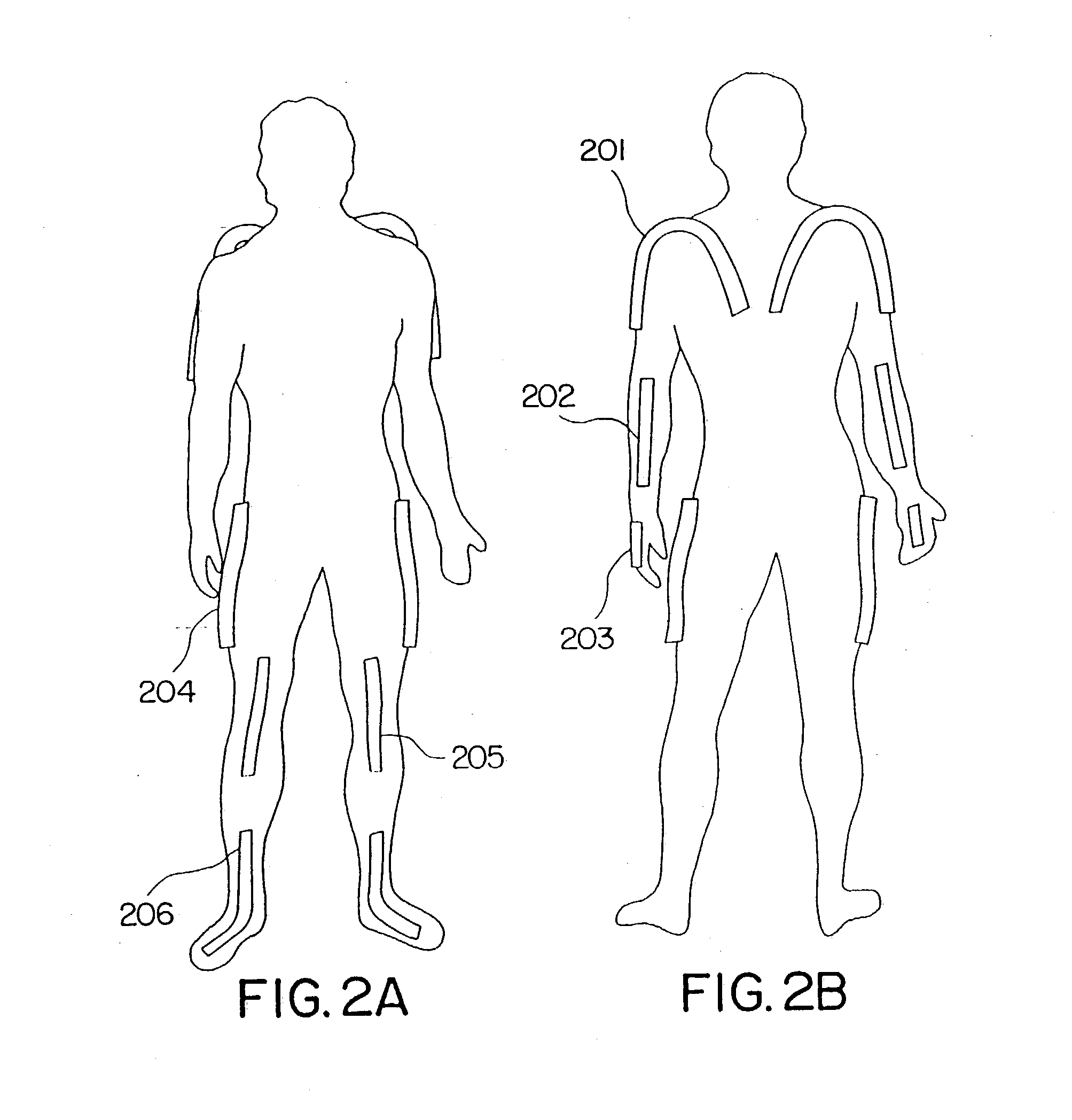
[0082] We now describe an overview of the inventive system and apparatus. In accordance with the subject invention, apparatuses are provided which employ multiple links connected by revolute joints, for measuring body parts, usually human body parts. The link and revolute joint assembly has terminal links for fitting to mounts for the body parts. The mounts secure the terminal links to the body part to minimize movement of the terminal links independent of the movement of the body part. Sensors are provided, where the sensor may extend past a plurality of joints or the sensor ...


PUM


Abstract

A sensing system is provided for measuring various joints of a human body for applications for performance animation, biomechanical studies and general motion capture. One sensing device of the system is a linkage-based sensing structure comprising rigid links interconnected by revolute joints, where each joint angle is measured by a resistive bend sensor or other convenient goniometer. Such a linkage-based sensing structure is typically used for measuring joints of the body, such as the shoulders, hips, neck, back and forearm, which have more than a single rotary degree of freedom of movement. In one embodiment of the linkage-based sensing structure, a single long resistive bend sensor measures the angle of more that one revolute joint. The terminal ends of the linkage-based sensing structure are secured to the body such that movement of the joint is measured by the device. A second sensing device of the sensing system comprises a flat, flexible resistive bend sensor guided by a channel on an elastic garment. Such a flat sensing device is typically used to measure various other joints of the body which have primarily one degree of freedom of movement, such as the elbows, knees and ankles. Combining the two sensing devices as described, the sensing system has low sensor bulk at body extremities, yet accurately measures the multi-degree-of-freedom joints nearer the torso. Such a system can operate totally untethered, in real time, and without concern for electromagnetic interference or sensor occlusion.

Description

[0001] This application is a continuation-in-part of U.S. Provisional Application Serial Nos. 60 / 044,495, filed Apr. 21, 1997, and 60 / 054,745, filed Aug. 4, 1997.RELEVANT LITERATURE[0002] U.S. Pat. No. 5,676,157, "Determination of Kinematically Constrained Multi-Articulated Structures", J. F. Kramer, describes kinematically constrained multi-articulated structures.BACKGROUND[0003] A growing market has developed for tools and systems that track humans and other bodies at rest and in motion. The applications for such systems vary considerably, and include such areas as the creation of computer-generated and graphical animations, the analysis of human-computer interaction, the assessment of performance athletics and other biomechanics activities, and the evaluation of workplace and other activities for general ergonomical fitness.[0004] The possible sample uses for a body-tracking system are wide and varied. For example, a user interested in creating a realistic computer animation of a...

Claims


Application Information

Patent Timeline
Patent Type & Authority Applications(United States)
IPC IPC(8): A61B5/103G06F3/00G06F3/01
CPCA61B5/1071A61B5/1116A61B5/1122A61B5/1124A61B5/4528A61B2562/043A61B5/6831G06F3/011A61B5/6806A61B5/6807A61B2562/0261A61B5/6804
Inventor KRAMER, JAMES F.ANANNY, JOHN M.BENTLEY, LOREN F.KORFF, PAUL L.BORONKAY, ALLEN R.MCNAMARA, CONOR
Owner IMMERSION CORPORATION
Why Eureka
Try Eureka