Implantation device for an aorta in an aortic arch

a technology for aortic arch and implantation device, which is applied in the field of arrangement for implantation in an aorta, can solve the problems of relative simplicity and avoid the effect of preventing the rupture of the arch, and reducing the time spen

a technology for aortic arch and implantation device, which is applied in the field of arrangement for implantation in an aorta, can solve the problems of relative simplicity and avoid the effect of preventing the rupture of the arch, and reducing the time spen

US20030097170A1Inactive Publication Date: 2003-05-22CURATIVE

Image

  • Implantation device for an aorta in an aortic arch
  • Implantation device for an aorta in an aortic arch

Examples


Embodiment Construction

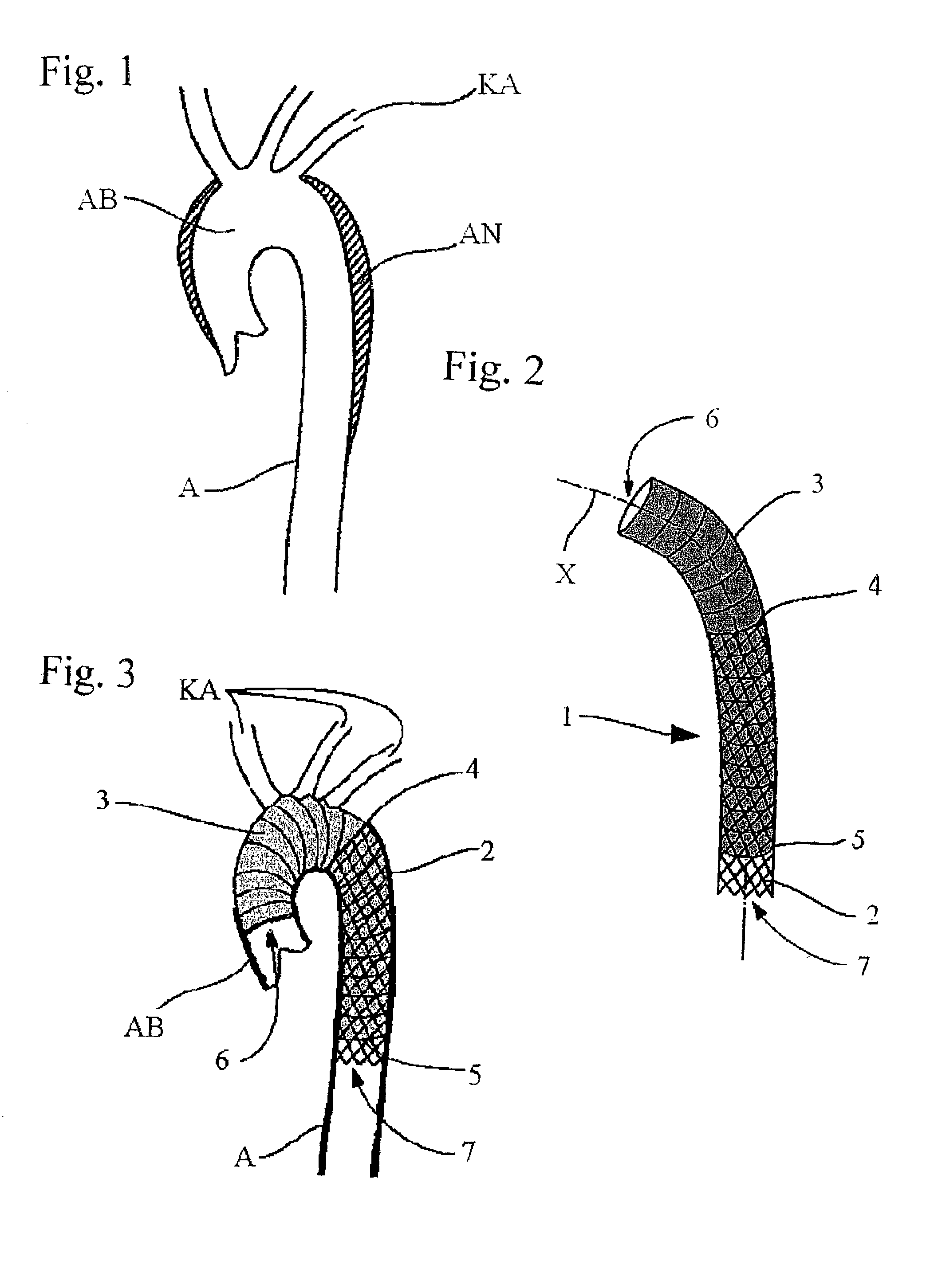
[0020] FIG. 1 illustrates an aorta in which aneurysms AN are present in the aortic arch AB on both sides of the cephalic arteries KA.

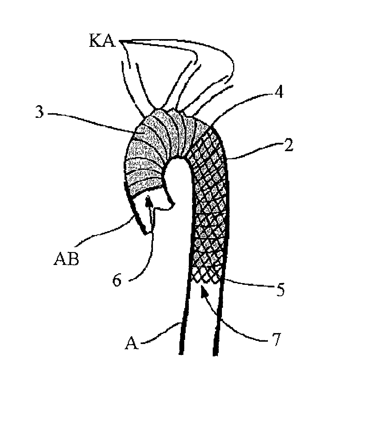
[0021] FIG. 2 shows an inventive implantable arrangement 1 which comprises a stent 2 of self-expandable tubular metal mesh fabric of Nitinol. This mesh is in the region between proximal end 4 and distal end 5 of a stent relative to a heart. This mesh is lined on its outside with Dacron having the same density as blood. Flexible tubing segment 3 functioning as a vascular prosthesis is formed by the extension of the lining of the same material disposed on a proximal part of stent 2. The longitudinal axis of implanted arrangement 1 is denoted by X. To prevent blockades of the vessels branching off from the aorta, the lining of stent 2 is expediently formed over only 80% of longitudinal direction X. The specific requirements for the length of stent 2 and of the lining as well as of free tubing segment 3 can be determined only after exact diagnosis of the d...


PUM


Abstract

A stent made of a self-expandable or balloon-expandable metal mesh fabric that can be widened to a diameter larger than that of the descending aorta. The stent has a flexible lining of vessel-replacing material, wherein the lining covers it at least partly in longitudinal direction and forms a tubular segment which projects beyond the end of the stent at least at one end and which functions as the vascular prosthesis. Such implantable arrangements (1) make it possible to achieve short surgical times, especially during the treatment of aortic arch aneurysms involving the cephalic arteries.

Description

CROSS REFERENCE TO RELATED APPLICATIONSBACKGROUND[0001] 1. Field of the Invention[0002] The invention relates to an arrangement for implantation in an aorta preferably in an aortic arch. The invention is used for treatment of aortic arch aneurysms and can be used during open-chest surgeries.[0003] 2. The Prior Art[0004] From practice, several implantation arrangements are known for treatment of stenosis tissue damage. One of the arrangements, for example, is a stent disposed permanently in the vessel. This stent is a spreading element made of self-expandable or balloon-expandable metal mesh fabric. It has been found, however, that a vascular stent becomes coated after several weeks by a new vascular inner wall, which can lead to a restenosis in narrow vessels (residual stenosis).[0005] U.S. Pat. No. 5,213,580 describes a balloon catheter with a coating of tissue-compatible plastic for treatment of vascular segments. This plastic seal is used to ensure that the vascular segment is he...

Claims


Application Information

Patent Timeline
22 May 2003
Publication
US20030097170A1
IPC
A61F2/06
CPC
A61F2/07; A61F2002/061; A61F2002/075; A61F2/90; A61F2002/072
Inventors
FRIEDRICH, HOLGER; CHAVAN, AJAY