

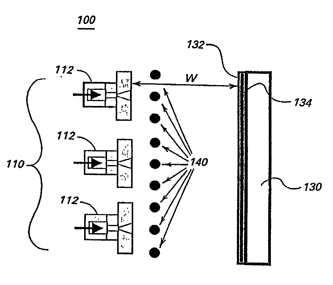
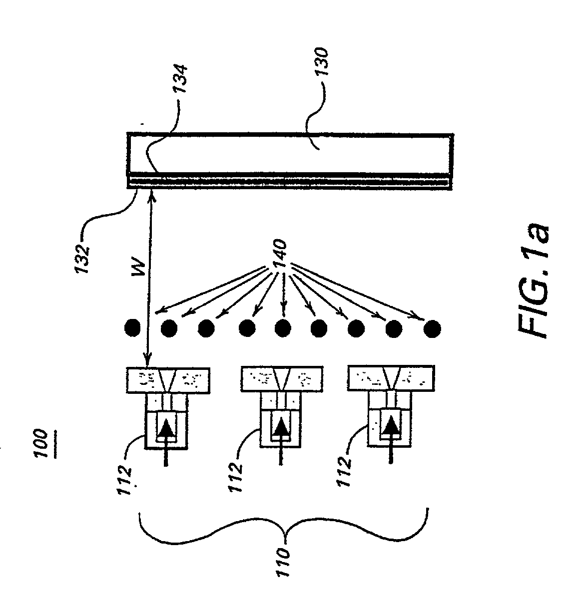
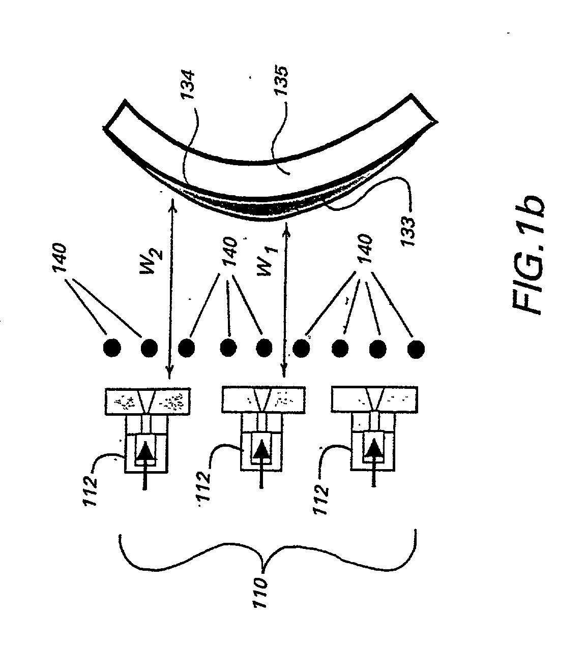
Apparatus and method for depositing large area coatings on non-planar surfaces
a technology of non-planar surfaces and apparatus, which is applied in the direction of coatings, plasma techniques, transportation and packaging, etc., can solve the problems of uniform coating of the substrate, inability of arrays of multiple plasma sources to uniformly coat such large non-planar surfaces, and adverse effects on coating uniformity
- Summary
- Abstract
- Description
- Claims
- Application Information
AI Technical Summary
Benefits of technology
Problems solved by technology
Method used
Image

Examples
Embodiment Construction
[0041] Experimental support for the invention is provided by carrying out experiments in which the precursor flow and the working distance w were varied. The substrate used was a flat polycarbonate substrate, as to better control the effects of these parameters. The ETP source was provided with a injector ring located in the expansion, or deposition, chamber and the reactant gas, or deposition precursor, was vinyltrimethylsilane (hereinafter referred to as "VTMS"). Flow between the VTMS reservoir to the injector ring was regulated and the pressure within the injector ring was monitored. The deposition experiments were performed using either 6 or 12 orifices in the injector ring. The ETP source was fed with 2 slm of argon and a current of 70 A was sent from the cathode to the anode of the ETP source to generate the thermal argon plasma. The pressure in the ETP source, or plasma, chamber was about 600 torr, whereas the pressure in the expansion chamber was about 35 millitorr.
[0042] Th...
PUM
| Property | Measurement | Unit |
|---|---|---|
| Pressure | aaaaa | aaaaa |
| Pressure | aaaaa | aaaaa |
| Pressure | aaaaa | aaaaa |
Abstract
Description
Claims
Application Information