
Method and a device for driving a liquid crystal display, and a liquid crystal display apparatus

Inactive Publication Date: 2003-06-05
MINOLTA CO LTD
View PDF8 Cites 19 Cited by
  • Summary
  • Abstract
  • Description
  • Claims
  • Application Information

AI Technical Summary

Benefits of technology

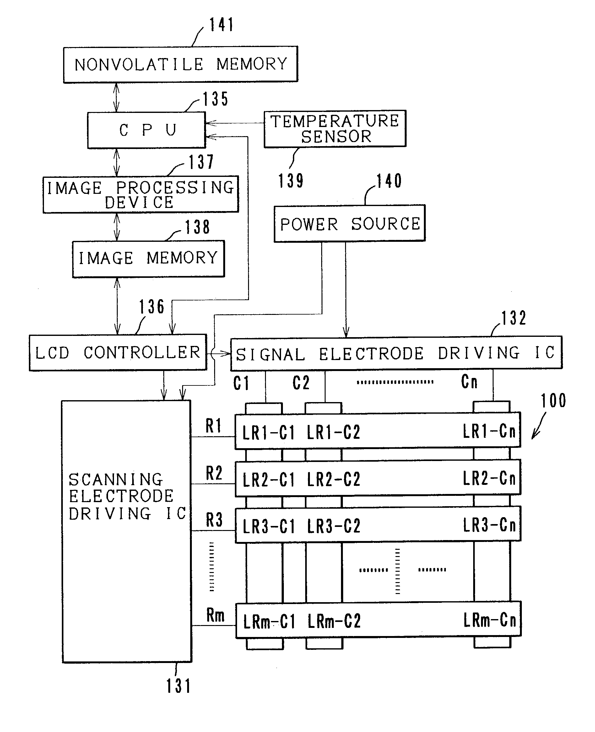
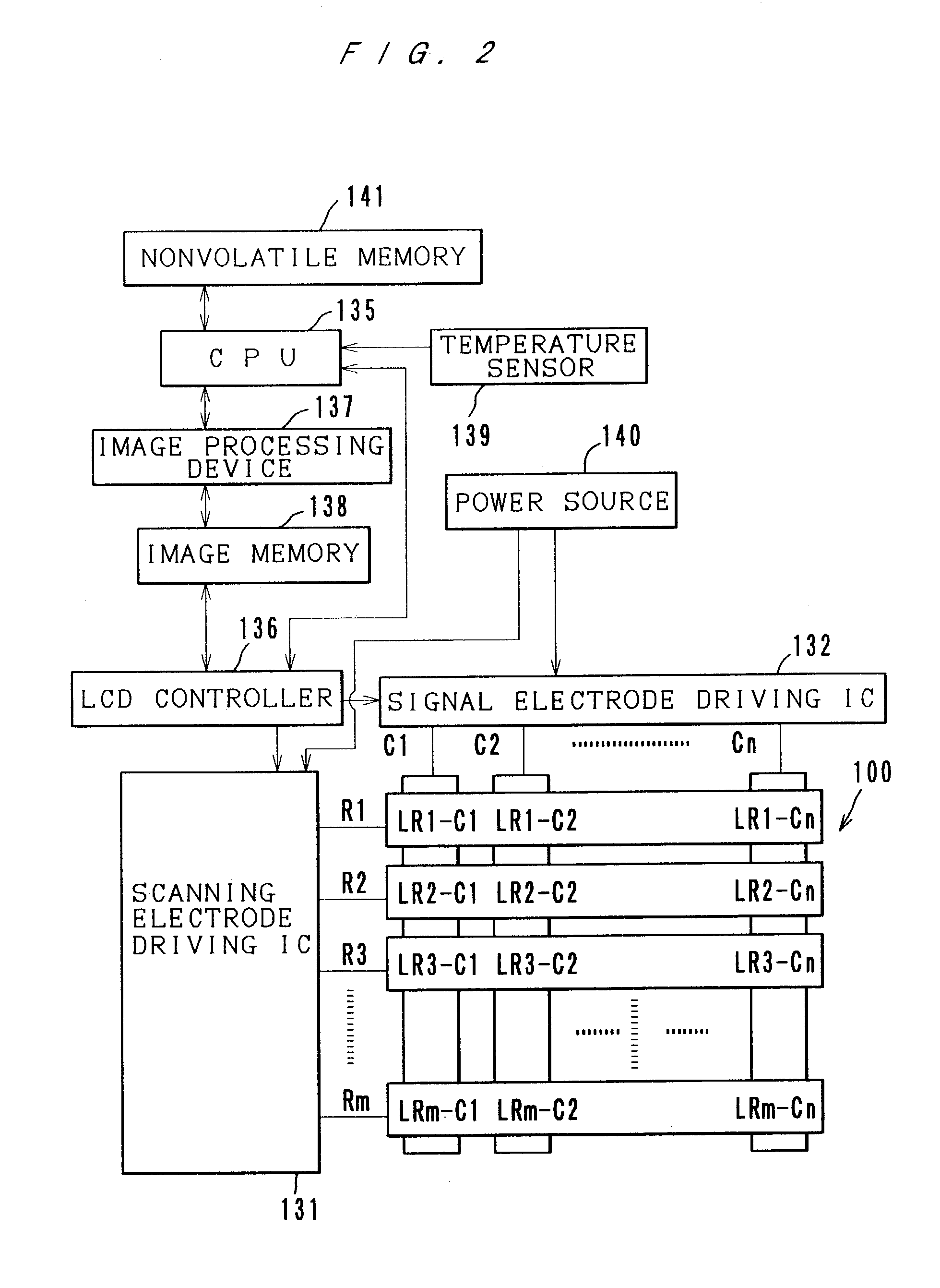
[0012] According to the first, second and third aspects of the invention, a delayed scanning mode is adopted. In the delayed scanning mode, in scanning of at least one set of scanning electrodes which are to be serially scanned, a delay step is inserted between a selection pulse application step of a previously scanned scanning electrode and a selection pulse application step of a later scanned scanning electrode is adopted. Thereby, the frequency of driving pulses can be lowered. Specifically, even if the circumstantial temperature rises, the frequency of driving pulses can be inhibited from becoming high, thereby preventing an increase in power consumption. When a delay step is inserted, the writing speed in a high temperature range is reduced a little but is not lower than the writing speed in a low temperature range.
[0019] The first, second and third aspects of the invention are applicable not only to progressive scanning in which scanning lines are scanned one by one progressively but also to interlace scanning in which one frame is divided into a plurality of fields and scanning lines are scanned with some lines skipped. Interlace scanning has the advantage of inhibiting blackout phenomena (occurrences of black lines on the screen) during image writing, and further, by applying the present invention to the interlace scanning, occurrences of ghost due to crosstalk can be inhibited.

Problems solved by technology

Such liquid crystal displays which use liquid crystal with a memory effect, however, have the disadvantage of having a low driving speed.
There is, however, a problem that as the frequency of driving pulses becomes higher, the consumption of electric power becomes larger.
In the above-described basic driving example, as temperature is rising, the driving frequency becomes higher, and accordingly the power consumption of the liquid crystal display apparatus becomes higher.

Method used


Image

  • Method and a device for driving a liquid crystal display, and a liquid crystal display apparatus
  • Method and a device for driving a liquid crystal display, and a liquid crystal display apparatus
  • Method and a device for driving a liquid crystal display, and a liquid crystal display apparatus

Examples


example 2

Driving Example 2; See FIG. 12

[0091] Next, driving example 2 which adopts the delayed scanning mode is described referring to FIG. 12. The pulse waves shown in FIG. 12 indicate the same things as those in FIG. 8.

[0092] Like the driving example 1, the driving example 2 is to inhibit the power consumption from being high in a high temperature range while being based on the basic driving example. What is different from the driving example 1 is that the column signal during each delay step Td is set to a pulse voltage for a display of a specified intermediate tone. There are essentially no image data in the delay steps; however, by applying a pulse voltage for a display of a specified gray level during each delay step, density differences among scanning lines can be inhibited. In this case, the strength of crosstalk becomes even without regard to the positions of the scanning lines.

example 3

Driving Example 3; See FIG. 13

[0093] Next, driving example 3 which adopts the delayed scanning mode is described referring to FIG. 13. The pulse waves shown in FIG. 13 indicate the same things as those in FIG. 8.

[0094] Like the driving example 1, the driving example 3 is based on the basic driving example and is to inhibit the power consumption from being higher in a high temperature range. Another purpose of the driving example 3 is to avoid occurrences of ghost in the pixels on non-selected scanning lines. What is different from the driving example 1 is to delay the selection pulse application step of every scanning line by a time of two units (Tsp.times.2). Therefore, this driving example 3 is referred to as a 1-2 delay mode. In this example 3, Tsp / Ts=1 / 3. As is apparent from FIG. 13, the voltage applied to the signal electrode becomes an alternated pulse voltage only during the selection pulse application step and is kept 0 volt during the other steps.

[0095] FIG. 13 shows a case...

example 4

Driving Example 4; See FIG. 15

[0099] The driving example 4 has the same purposes as the driving example 3, and additionally, the driving example 4 is to shorten the scanning time. What is different from the driving example 3 is to delay the selection pulse application step of every scanning line by a time of three units (Tsp.times.3). Therefore, this is referred to as a 1-3 delay mode. In the driving example 3, Tsp / Ts=1 / 5. The time required for scanning one frame in this example 4 is {fraction (9 / 10)} of that in the driving example 3. In this driving example 4 also, the voltage applied to the signal electrode becomes an alternated pulse voltage only during the selection pulse application step and is kept 0 volt during the other steps.

[0100] Like FIG. 13, FIG. 15 shows a case of writing intermediate tones in LCD1 and LCD2 and writing the densest image (reflection) in LCD3 and LCD4. Focusing on the pixel LCD3, in this driving example 4 also, crosstalk does not occur during the steps A...


PUM


Abstract

Disclosed herewith is a matrix driving method of liquid crystal which exhibits a cholesteric phase. In the method, there is a selection pulse application step of applying pulses to select the final state of the liquid crystal, and between the selection pulse application step of a scanning line and the selection pulse application step of the next scanned scanning line, a delay step is inserted. During the delay step, a signal pulse is of 0V or of a pulse voltage for a display of a specified density.

Description

[0001] This application is based on Japanese patent application Nos. 2001-367963 and 2002-40853, the contents of which are herein incorporated by reference.[0002] 1. Field of the Invention[0003] The present invention relates to a method and a device for driving a liquid crystal display and a liquid crystal display apparatus, and more particularly to a method and a device for driving a liquid crystal display by applying pulse driving voltages to liquid crystal through a plurality of scanning electrodes and a plurality of signal electrodes which cross each other at a right angle and a liquid crystal display apparatus.[0004] 2. Description of Related Art[0005] In recent years, as media for reproducing digital information as visual information, reflective type liquid crystal displays which use liquid crystal which exhibits a cholesteric phase at room temperature (typically, chiral nematic liquid crystal) have been studied and developed into various kinds because such liquid crystal disp...

Claims


Application Information

Patent Timeline
IPC IPC(8): G09G3/20G02F1/133G09G3/36
CPCG09G3/3629G09G2310/065G09G2300/0486
Inventor YAMAKAWA, EIJIMASAZUMI, NAOKI
Owner MINOLTA CO LTD
Learn More