Slotting cutter and cutting insert there to

Inactive Publication Date: 2003-06-05
HOGANAS AB +1
View PDF9 Cites 15 Cited by
  • Summary
  • Abstract
  • Description
  • Claims
  • Application Information

AI Technical Summary

Problems solved by technology

However, in this case the cutting inserts are not dismountable and indexabl

Method used


Image

  • Slotting cutter and cutting insert there to
  • Slotting cutter and cutting insert there to
  • Slotting cutter and cutting insert there to

Examples


Example

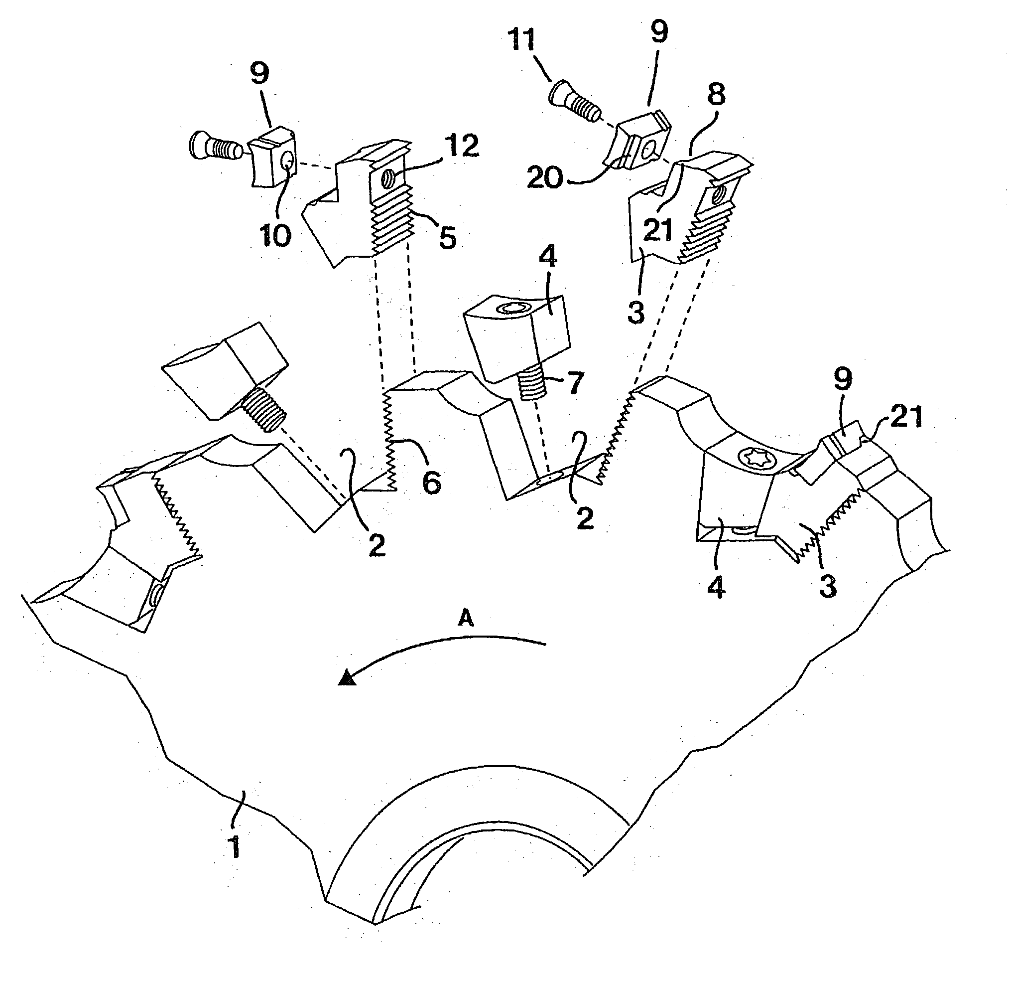
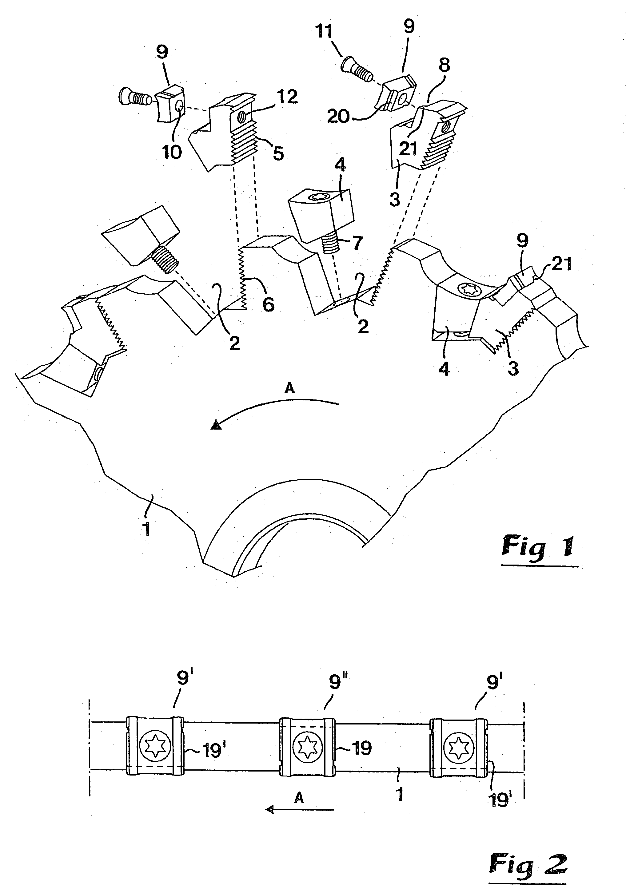
[0023] In FIG. 1 a slotting cutter is illustrated which includes a circular disc 1 being rotatable around a central axis of rotation (not shown), more precisely in the direction of the arrow A. Along the periphery of the disc, a plurality of tangentially spaced chip channels 2 are formed, each one of which houses a cassette 3, as well as a wedge 4 for fixing of the cassette. In order to secure the cassette 3 reliably, the same is formed with a serration 5 co-operating with a corresponding serration 6 in a rear wall of the chip channel. The wedge 4 is tightenable by means of a screw 7. In each cassette 3, a seat 8 is formed for the receipt of a cutting insert 9. In said cutting insert, there is a central hole 10 for a fixing screw 11, which is tightenable in a threaded hole 12 in the cassette.

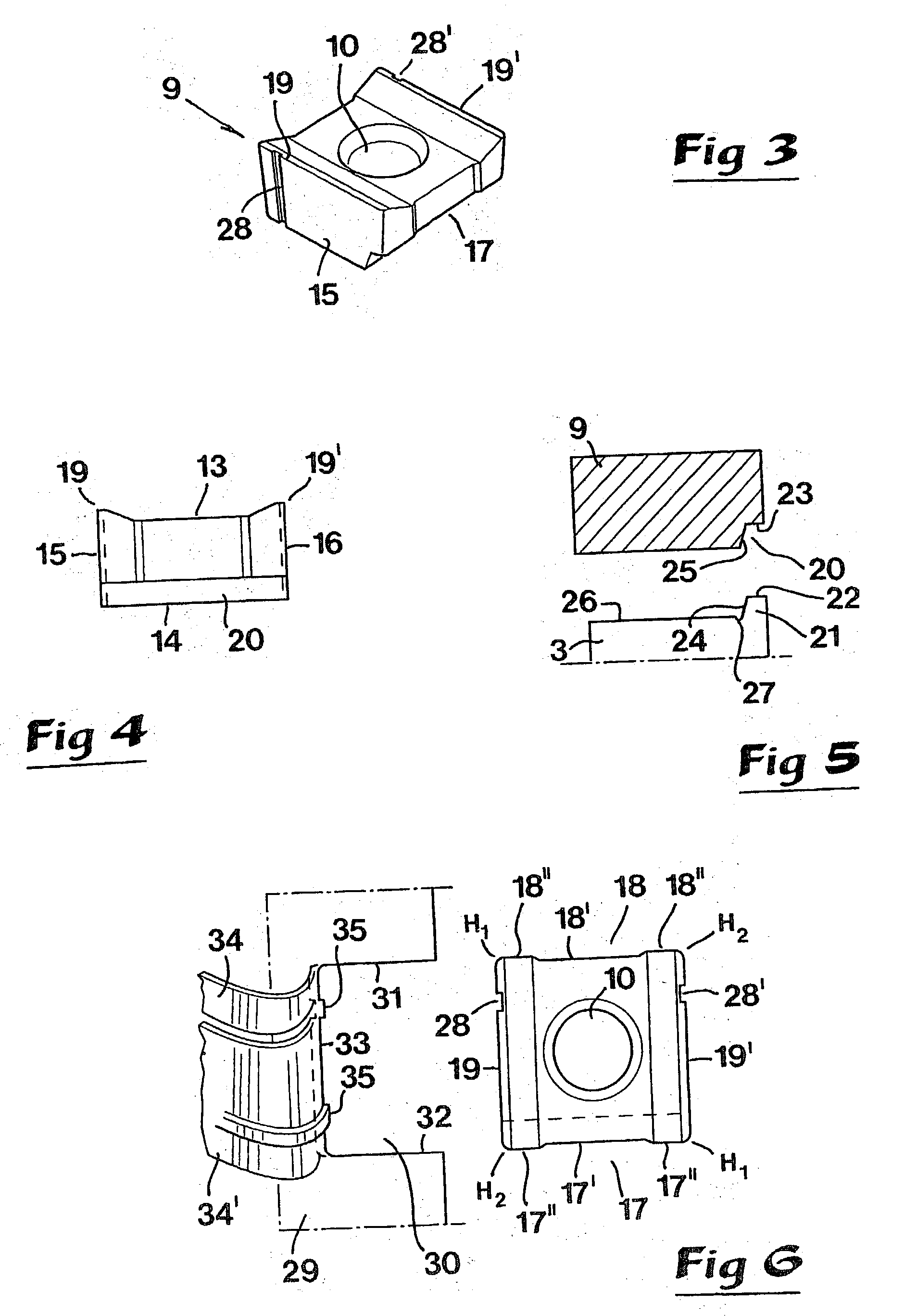
[0024] As is best seen in FIGS. 3-5, the cutting insert 9 consists of a flat body having a quadrangular basic shape which is delimited by a top side 13, a bottom side 14, first and second end su...


PUM

PropertyMeasurementUnit
Heightaaaaaaaaaa

Abstract

A slotting cutter includes a circular disc having an outer periphery along which a plurality of chip channels are formed which define respective seats for receiving respective index able cutting inserts. Each insert includes a planar bottom side. Either the seat or the bottom side has a male locator portion, and the other of the seat and the bottom side has a female locator portion which receives the male locator portion to define therewith and insert-locating structure. The male and female locator portions are offset laterally from a center plane of the insert oriented perpendicular to an axis of rotation of the disc. Alternating ones of the insert-locating structures are disposed on respective opposite sides of the center plane.

Description

[0001] In a first aspect, this invention relates to a slotting cutter of the type that comprises a circular disc along the periphery of which a plurality of tangentially spaced chip channels are formed, which house seats for indexable cutting inserts having a width which is larger than the thickness of the disc in order that the inserts can mill out a groove that is delimited by two parallel side surfaces and a bottom, during the milling of a workpiece, the cutting inserts having means for dividing the material which is separated from the bottom of the cutting groove into two or more partial chips.[0002] Slitting cutters and slotting cutters should be considered as being the same.PRIOR ART[0003] Modern slotting cutters of the general type given above usually make use of special cassettes for mounting the cutting inserts. Said cassettes are formed with a seat for the indexable cutting insert, as well as a serration for engagement with an analogous serration formed in the cutter disc ...

Claims


Application Information

Patent Timeline
IPC IPC(8): B23C5/08B23C5/20B23C5/22
CPCB23C5/08B23C5/202B23C5/2226B23C2200/125B23C2200/126Y10T407/2202B23C2200/205B23C2220/36B23C2260/80Y10T407/1922Y10T407/1932B23C2200/128
Inventor ASTROM, WILLY
Owner HOGANAS AB
Why Eureka
Try Eureka