
Method and device relating to coating a running web

a running web and running web technology, applied in the direction of liquid surface applicators, special surfaces, pretreated surfaces, etc., can solve the problems of affecting the operation and quality, the web material is not fully utilized, and the risk of tension in the edge zone, so as to reduce the noise level and counteract the tacking problem

Inactive Publication Date: 2003-06-05
UMV COATING
View PDF2 Cites 22 Cited by
  • Summary
  • Abstract
  • Description
  • Claims
  • Application Information

AI Technical Summary

Benefits of technology

[0010] Still another purpose of the invention is to make coating of the entire web possible, not only in connection with double-sided coating, but also in connection with single-sided coating.
[0011] Preferably, it is also a purpose of the invention to eliminate or at least to reduce the above mentioned problems caused by blade wear in connection with non-entire width coating.
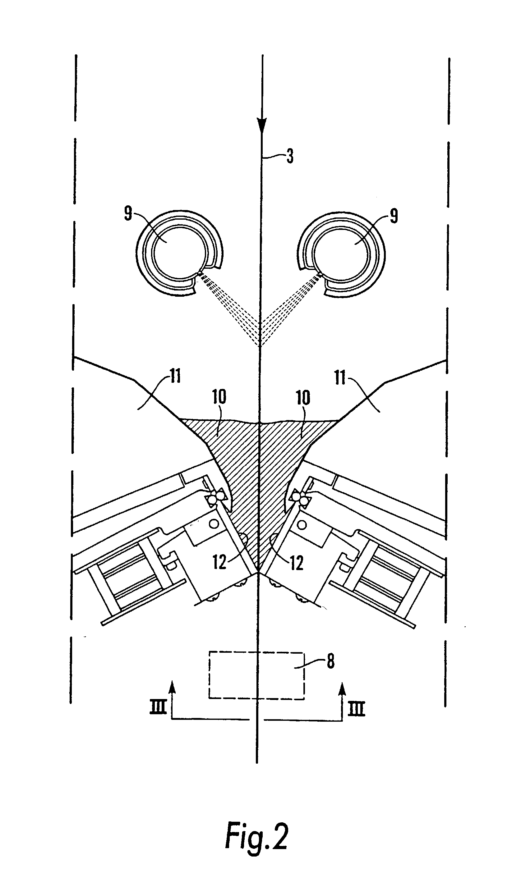
[0012] These and other objectives can be achieved therein that the existing excess of coating mixture in or adjacent to the regions of the edge portions of the web is removed by being blown off. More particularly, the said excess of coating mixture in the region of each of the edge portions of the web is removed by means of compressed-air in the form of one or more compressed-air jets, while the coating mixture still is in a liquid state. By preheating the compressed-air it is also possible to achieve an improved evaporation of the coating mixture, which further ensures that the coating mixture in the edge portions has reached its point of immobilisation before it is brought in contact with any rolls.
[0019] The nozzles may have various designs. According to the chosen embodiment, the nozzles have a circular outlet opening, but they may also be designed for instance with a longitudinal, slot-shaped outlet opening. In the latter case, the longitudinal, slot-shaped outlet opening is suitably arranged in parallel with or at an angel to the web edge. Also special air nozzles designed in order to reduce the noise level can be conceived. It is also possible on each side of the web material, at a distance inside of each web edge, to provide a series of a plurality of nozzles after one another in the longitudinal direction of the web, wherein each such nozzle may be directed in the same mode or in different directions in order to provide best blowing-off effect.
[0021] The device of the invention preferably also comprises means for collecting and leading away the coating mixture that has been blown off from the web edge regions. These means may for instance include a collecting funnel placed at a distance, e.g. about 2 to 5 cm, outside of each web edge, the centre of the funnel being located approximately aligned with the web line. The mouth of the funnel may be provided with one or more water spraying nozzles, suitably nozzles of the type that spray flat water jets, intended to form a curtain of water in the mouth of the funnel. The funnel or the like suitably is designed such that the removed coating mixture is caused to pass through the water curtain and be mixed with water as it passes through the water curtain, whereupon the mixture is trapped in the funnel and conveyed to a suitable re-circulation or waste system via a pipe system. In a particularly preferred embodiment the walls of the funnel or corresponding member are cooled, e.g. by cooling water circulating in the walls of the funnel in order to provide a condensation on the surface and therein prevent deposition of coating mixture and to facilitate cleaning of the equipment.
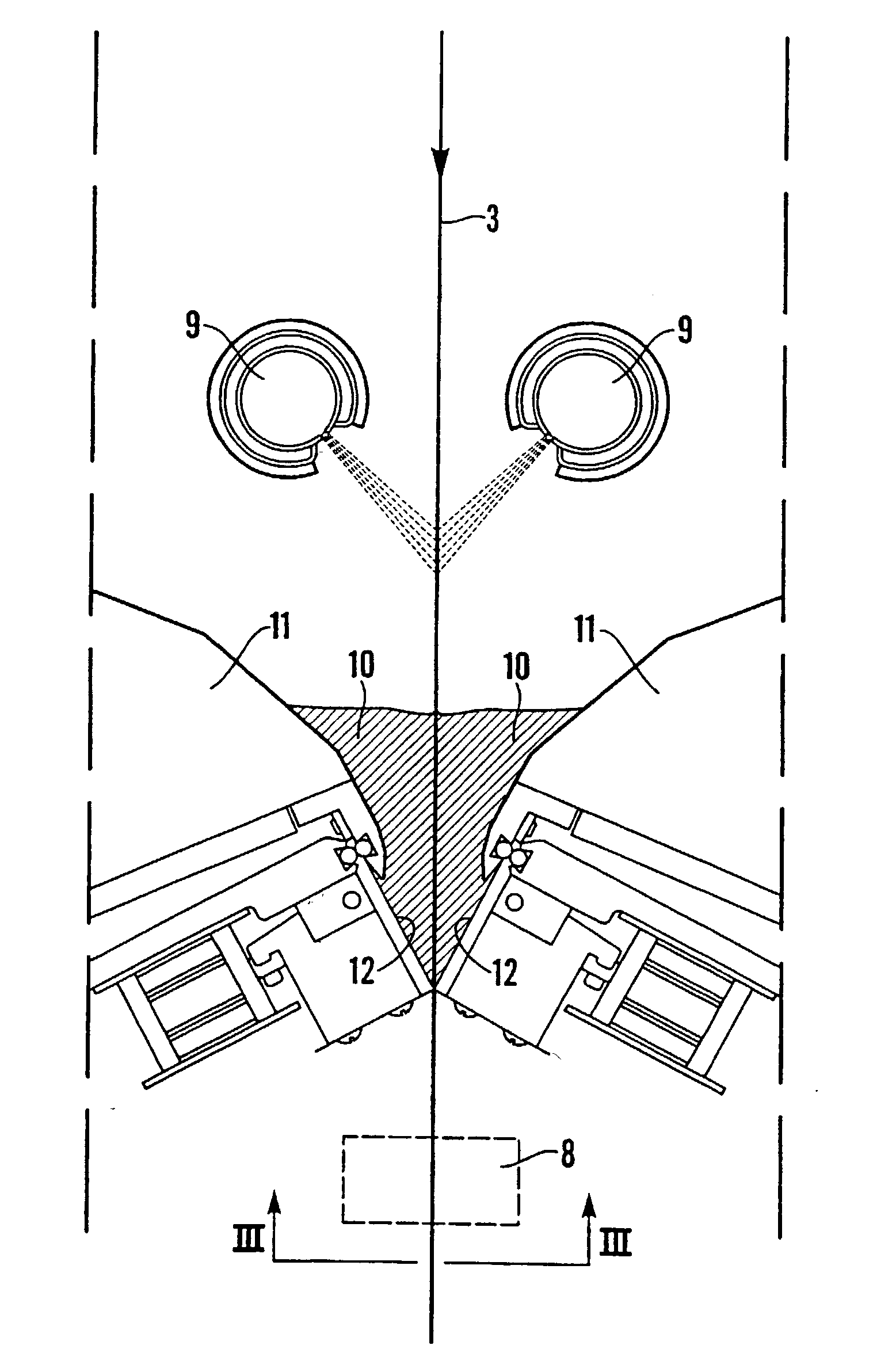
[0027] FIG. 4 illustrates a second application of the invention for the removal of excess of coating mixture in the form of strands at a short distance from the web edges.

Problems solved by technology

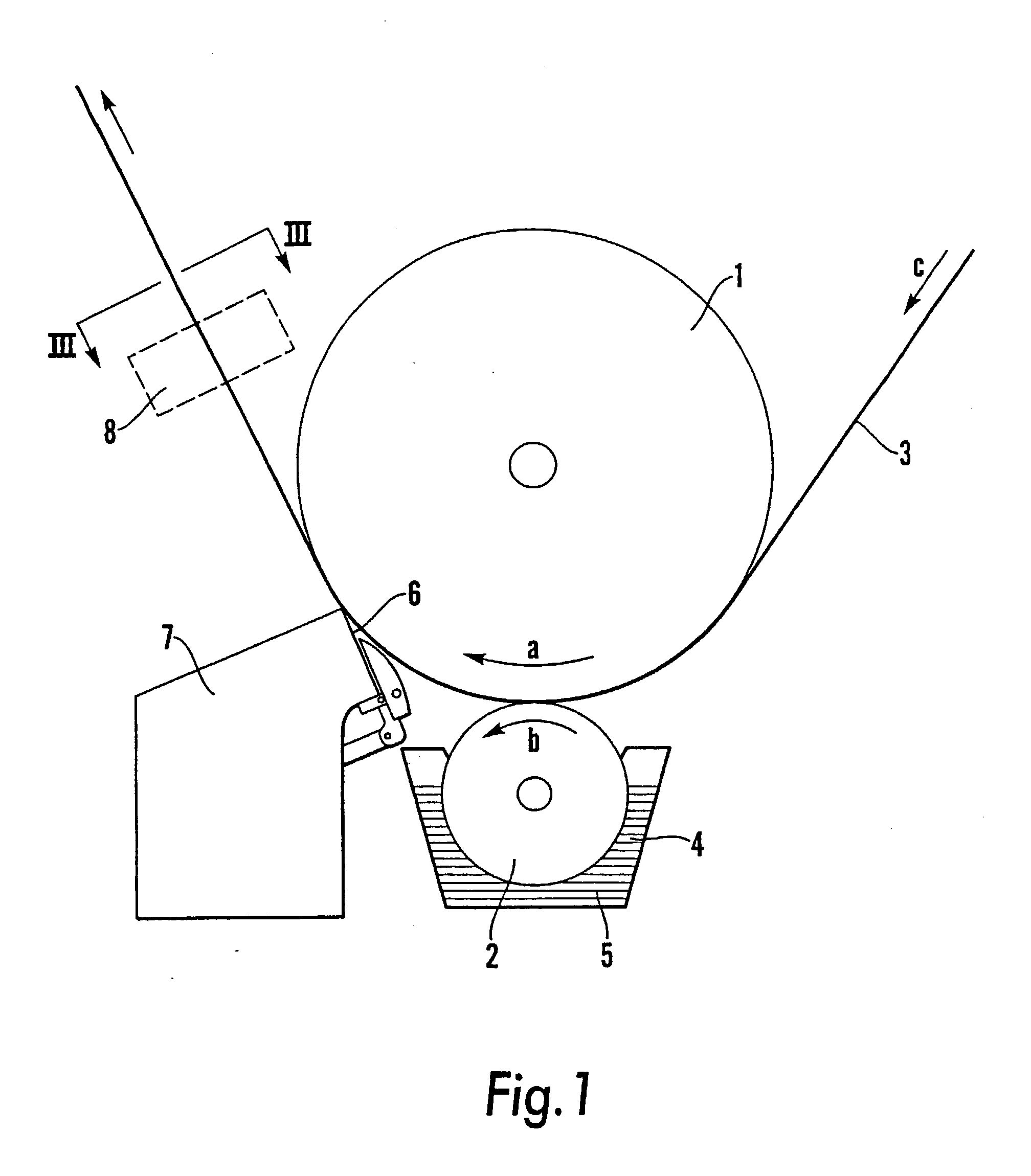
The coating mixture which is applied on the edge surfaces also, when only one surface is being coated, partly passes over to the opposite, uncoated side of the web, and since this side has contact with rolls as the web is transported in the coating machine before the coating mixture has dried to its so called point of immobilisation (i.e. to tack-free state), coating mixture will deposit on said rolls, which gives rise to problems concerning operation and quality.
However, a drawback with that technique is that the web material is not fully utilized because uncoated edge zones must be cut off.
Another drawback is that the edge zones are not supplied with the same amount of liquid as the coated region, which poses a risk of tensions in the edge zones and at worse ruptures in the edge regions.
Another problem is that the end portions of the coater blade is subjected to more severe wear, i.e. the portions which correspond to the border zones between the coated surface and the uncoated edge portions of the web.
Therefore, more liquid is absorbed in the border zones than in the region of the coated surface inside of the edge, which leads to the formation of border zones containing dryer coating mixture and therefore more severe wear.
The greater wear in the said zone in the course with time will result in a thicker deposition of coating mixture in the border zones, i.e. excess of coating mixture in those zones which do not get ample time to dry to the point of immobilisation of the coating mixture before it contacts rolls, which also gives rise to problems because of depositions on drying cylinders and guide rolls.
Also in that case, more liquid in the form of coating mixture is absorbed by the web edges than by the web surfaces, which may cause that the edges have not reached a tack-free dry content level when the web is brought into contact with web guiding rolls or drying cylinders.

Method used


Image

  • Method and device relating to coating a running web
  • Method and device relating to coating a running web
  • Method and device relating to coating a running web

Examples


example

[0037] The example relates to application of the invention for double-sided coating of a running paper web right out to the web edges by means of opposite blades, FIG. 2. At a test, the equipment which has been described with reference to FIG. 3 was employed. At the test, the excess of coating mixture, that was blown off from the edge, and water from the water curtain, which was passed by the blown-off mixture, were collected in a container during a certain period of time. The collected liquid was evaporated and the content of dry matter was measured. The measurements indicated an evident reduction of coating mixture on the edge.

[0038] Practical measurements also were made during the test through observation of depositions of coating mixture on the drying cylinders of the machine downstream of the coater assembly. These observations indicated that no deposition of coating mixture on the web edges or on the drying cylinders could be found as long as the air nozzles were connected to ...


PUM


Abstract

When a running web (3) is coated with a liquid coating mixture, at least one side of the web is provided with a coating (40, 40') of coating mixture. Existing excess (33) of coating mixture in or adjacent to the regions of the edge portions of the web is removed by being blown off downstreams of where the coating operation is performed.

Description

[0001] The invention relates to a method for coating a running web with liquid coating mixture, so that at least one side of the web is provided with a coating of a coating mixture. The invention also relates to a device for carrying out the method. The web preferably is a web which completely or partly consists of a cellulose-containing material, e.g. a paper web or a paper board web.[0002] Doctor blade coating is a coating method where a web, e.g. a web of paper, paper board or other cellulose-containing material, which contacts a support member, e.g. a roll, is supplied with a coating mixture in excess in a first step. The coating mixture may have the form of a more or less viscous liquid, usually referred to as coating paste. In this text, however, the term coating mixture is used. In the next step, excess of coating mixture is scraped off and the coating layer is evened by means of a so called coating blade. According to conventional technique the coating blade consists of a re...

Claims


Application Information

Patent Timeline
Patent Type & Authority Applications(United States)
IPC IPC(8): B05C1/08B05D1/28B05C9/04B05C11/04B05C11/06B05C11/10B05D3/00D21H25/16
CPCB05C1/083B05C9/04D21H25/16B05C11/06B05C11/1039B05C11/04
Inventor KARLSSON, HAKAN
Owner UMV COATING
Learn More