Optical disk for high resolution and three-dimensional video recording, optical disk reproduction apparatus, and optical disk recording apparatus

a technology of optical disks and recording devices, applied in the field of optical disks for high resolution and three-dimensional video recording, optical disk reproduction devices, optical disk recording devices, etc., can solve the problems of synchronization system, inability to perform compensation, and incompatibility of conventional 3d and high-definition optical disks with ordinary optical disks

Inactive Publication Date: 2003-06-12
PANASONIC CORP
View PDF5 Cites 87 Cited by
  • Summary
  • Abstract
  • Description
  • Claims
  • Application Information

AI Technical Summary

Benefits of technology

[0517] A basic video signal and an interpolation signal are divided into frames each having 1 GOP or more and subjected to interleaving alternately to be recorded on the optical disk as interleave blocks 54 and 55. From such an optical disk, a progressive / 3D reproduction apparatus reproduces both information in the interleave block for the odd field (right eye) and information in the interleave block for the even field (left eye). Thus, a progressive / 3D picture is obtained. A non-progressive / 3D reproduction apparatus reproduces information in the interleave block of only odd field (right eye) or even field (left eye) by track jump. Thus, a complete two-dimensional picture is obtained. Thus, compatibility is realized.
[0518] Especially, a progressive / 3D picture arrangement information file and a progressive / 3D picture identifier are recorded on the optical disk. Accordingly, the location of the progressive / 3D is easily determined. Therefore, two ordinary interlace signals can be made into a progressive signal. Furthermore, it can be avoided that pictures for the right eye and left eye of different contents are output on the 3D TV.
[0519] In a 3D reproduction apparatus, a pointer used for two-dimensional display is used when an 3D identifier is available to change the access process. Thus, 3D pictures can be continuously displayed. Moreover, a 3D reproduction apparatus is realized without changing the two-dimensional format.
[0520] According to the synchronization method of the present invention, a plurality of video signals or a plurality of audio signals to be simultaneously reproduced are extended in synchronization for reproduction.
[0521] In the embodiment where a horizontal synchronization signal and a vertical synchronization signal which are output from one video decoder are used as the horizontal synchronization signal and the vertical synchronization signal of another video decoder, synchronization on a pixel-by-pixel basis is realized even when, for example, a plurality of compression video signals are extended and the extended signals are synthesized into a 3D picture or a high resolution picture.
[0522] In a reproduction apparatus in which the reference time signal is corrected using an APTS detected by an audio decoder and the video output timing is controlled so that the VPTS matches the corrected reference time signal, an audio signal and a plurality of video signals are synchronized for reproduction with no unnaturalness in the audio output.
[0523] In a reproduction apparatus in which the audio output timing is controlled by changing an extension clock, audio and video signals are synchronized for reproduction with no unnaturalness in the audio output with no interruption or pause in the audio signal.

Problems solved by technology

A first problem of the conventional art will be described.
In other words, the conventional 3D and high definition optical disks are not compatible with ordinary optical disks.
A second problem of the conventional art concerns a synchronization system.
The conventional synchronization system has problems in that, for example, when the data becomes out of synchronization for some reason during reproduction, compensation is not performed; and that audio data is not synchronized.

Method used


Image

  • Optical disk for high resolution and three-dimensional video recording, optical disk reproduction apparatus, and optical disk recording apparatus
  • Optical disk for high resolution and three-dimensional video recording, optical disk reproduction apparatus, and optical disk recording apparatus
  • Optical disk for high resolution and three-dimensional video recording, optical disk reproduction apparatus, and optical disk recording apparatus

Examples


example 2

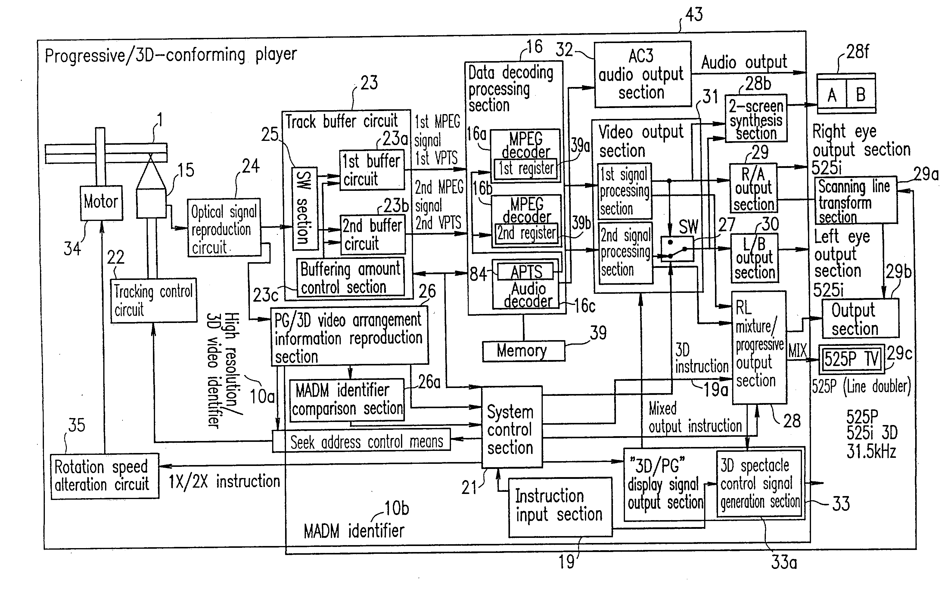
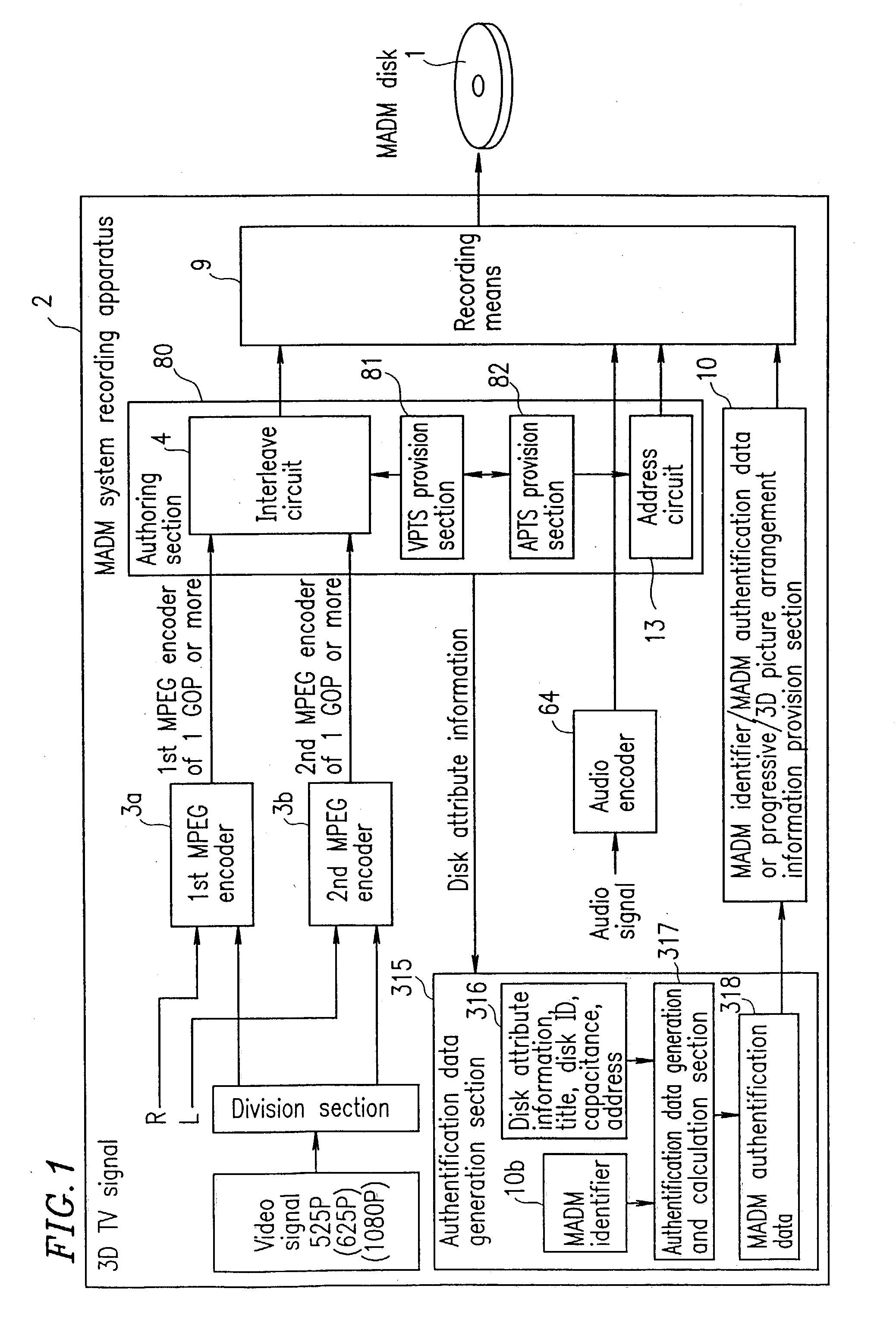
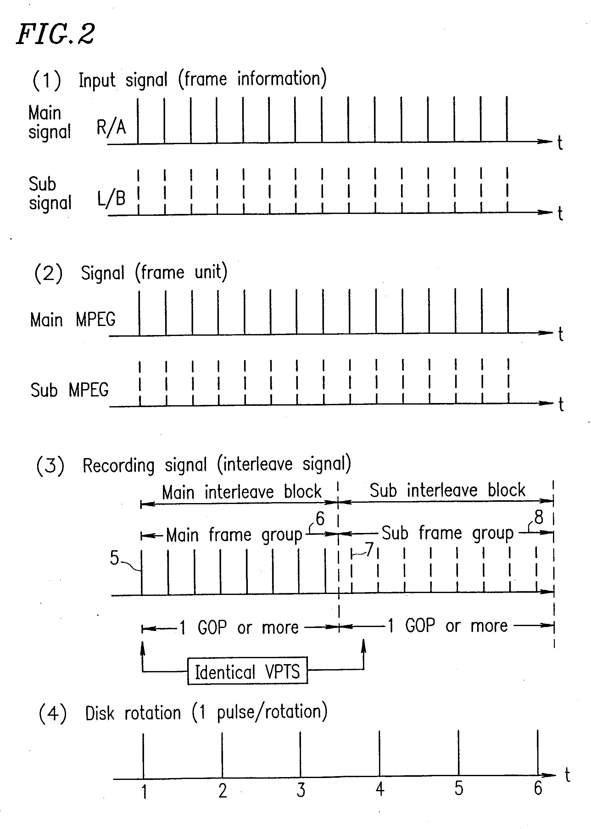
[0396] The MADM system according to the present invention simultaneously reproduction of a plurality of streams. Synchronization methods are important. In the second through eighth examples, various methods of synchronization will be described. The MADM system is also applicable to recording and reproduction of high resolution pictures such as 3D or 525P pictures, which will not be described below.

[0397] As an example, in the second example, an operation of a reproduction apparatus for reading data from an optical disk having three compression video signals to be reproduced simultaneously and extending and reproducing the three compression video signals simultaneously will be described.

[0398] FIG. 66 shows a data structure of the optical disk used in the optical disk reproduction apparatus in the second example.

[0399] Video signals A, B and C are MPEG-compressed to obtain compression video streams A, B and C.

[0400] The compression video streams A, B and C are each packeted in units ...

example 3

[0427] The third example relates to a reproduction apparatus for correcting a reference time signal using audio reproduction time information indicating the time to reproduce the audio signal and synchronizes a plurality of video signals based on the reference time signal.

[0428] FIG. 70 shows a data structure of the optical disk used in the optical disk reproduction apparatus in the third example. The optical disk includes compression audio data in addition to the data included in the optical disk used in the second example.

[0429] An audio signal is audio-framed in units of 32 msec. for compression to obtain a compression audio stream. The audio stream is packeted in units of 2 kB into audio packets and recorded on the optical disk. A packet header of each audio packet includes a stream ID for indicating that the stored data is a compression audio stream. When the packet stores a leading part of the audio frame, the packet header also includes APTS (audio presentation time stamp) as...

example 4

[0450] The fourth example relates to a reproduction apparatus for correcting the reference time signal using a VPTS detected by one video decoder and synchronizing a plurality of video signals based on the reference time signal.

[0451] FIG. 72 is a block diagram of an optical disk reproduction apparatus in the fourth example.

[0452] Elements 501 through 532 are the same as those in the second example. Reference numeral 551 represents a video decoder used in the fourth example.

[0453] The video decoder 551 has a function of outputting the detected VPTS. FIG. 73 shows a structure of the video decoder 551.

[0454] The video decoder 551 includes VPTS detection means 801 for detecting a VPTS indicating the reproduction time of the video signal multiplexed as the compression video signal and video extension means 802 for extending the compression video stream.

[0455] In the fourth example, due to the precision error of the crystal oscillator used in the reference time signal generation means 50...


PUM

PropertyMeasurementUnit
field frequencyaaaaaaaaaa
timeaaaaaaaaaa

Abstract

The present invention has an objective of providing an optical disk having a high resolution picture and a system for reproducing data on the optical disk, which are compatible with a conventional system for reproducing an ordinary resolution picture. A high resolution signal is divided into a main signal and a sub signal by picture division means and MPEG-encoded. The main signal and the sub signal are divided into frames each having 1 GOP or more. The resultant first interleave block 54 and second interleave block 55 are recorded alternately on an optical disk. A high resolution reproduction apparatus reproduced both the first and second interleave blocks, so that a high resolution picture is obtained. A non-high resolution reproduction apparatus reproduces only the first or second interleave block, so that an ordinary resolution picture.

Description

[0001] The present invention relates to an optical disk having a three-dimensional (3D) picture and a high definition picture stored thereon, and an apparatus for recording data to or reproducing data from the optical disk.[0002] A conventionally known optical disk having a 3D moving picture stored thereon is as shown in FIG. 10. An optical disk 201 has a picture for the right eye (right-eye picture) stored in even fields 204, 204a and 204b and a picture for the left eye (left-eye picture) stored in odd fields 203, 203a and 203b. The right-eye picture and the left-eye picture are recorded alternately. When the data stored on the optical disk 201 is reproduced by an existing optical disk reproduction apparatus 205 shown in FIG. 11, a right-eye picture and a left-eye picture appear on a TV screen 206 alternately every {fraction (1 / 60)} second. The naked eye recognizes only a picture in which the right-eye picture and the left-eye picture are overlapped. With 3D spectacles 207, in whic...

Claims


Application Information

Patent Timeline
Patent Type & Authority Applications(United States)
IPC IPC(8): G11B7/00G11B7/0037G11B7/004G11B7/007G11B20/10G11B20/12H04N5/04H04N5/44H04N5/45H04N5/46H04N5/85H04N5/91H04N5/92H04N5/93H04N7/50H04N9/79H04N9/804H04N9/806H04N9/82H04N9/877H04N13/239
CPCG11B20/00007H04N13/0062G11B20/10527G11B20/1217G11B20/14G11B27/005G11B27/10G11B27/105G11B2020/10546G11B2020/10675G11B2020/1074G11B2020/10805G11B2020/10953G11B2020/1288G11B2220/2562H04N5/04H04N5/4401H04N5/45H04N5/46H04N5/765H04N5/775H04N5/85H04N7/012H04N7/0122H04N9/7921H04N9/8042H04N9/8045H04N9/8063H04N9/8205H04N9/8227H04N9/877H04N13/0003H04N13/0033H04N13/0037H04N13/0048H04N13/0051H04N13/0055H04N13/0059H04N13/0066H04N13/007H04N13/0239H04N13/0438H04N13/0454H04N13/0456H04N13/0459H04N13/0497H04N2013/0085H04N19/597H04N19/61G11B20/10222H04N21/42646H04N21/4305H04N21/4325H04N21/4334H04N21/4392H04N13/341H04N13/167H04N13/194H04N13/189H04N13/183H04N13/161H04N13/144H04N13/363H04N13/10H04N13/15H04N13/359H04N13/239H04N13/361H04N13/178H04N13/398H04N13/172H04N21/426H04N21/43072H04N13/00
Inventor OSHIMA, MITSUAKIKITAURA, HIROMUFUKUDA, HIDEKIISHIHARA, HIDESHIKAWARA, TOSHIYUKI
Owner PANASONIC CORP
Why Eureka
Try Eureka