Device and method for controlling operation of legged robot, and robot device

Inactive Publication Date: 2003-06-26
SONY CORP
View PDF5 Cites 53 Cited by
  • Summary
  • Abstract
  • Description
  • Claims
  • Application Information

AI Technical Summary

Benefits of technology

0098] According to the robot apparatus in accordance with the fifth aspect of the present invention, when a motion pattern of the robot body consisting of the combined motions of the upper limbs, the trunk, and the lower limbs is performed, the motion pattern is modified by calculating the upper limb motion for canceling the yaw-axis moment generated on the robot body at the preset ZMP. With this calculation, a whole-body coordinated motion is achieved stably and accurately while canceling the affect of the yaw-axis moment applied on the robot body during a leg-moving operation.
0099] Especially in a biped walking robot, a yaw-axis moment applied o

Problems solved by technology

Among others, legged walking robots have advantages in moving up and down stairs and a ladder, walking over an obstacle, and a flexible walk and walking motion regardless of leveled and unleveled terrain, although these robots are more unstable and more difficult in controlling an attitude and a walk than crawler-type robots and tired mobile robots.
An attitude stabilization control of a robot is extremely important for preventing the robot from falling down, because falling-down leads to suspending the performing operation of the robot and also requires a considerable amount of labor and time for standing up and restarting the operation from falling down.
More importantly, falling-down of the robot causes a risk of a fatal damage to the robot itself or to an opposing obstacle colliding with the falling robot.
Such a yaw-axis moment acts to rotate the robot body in the course of time, thereby causing a slip about yaw axis between the foot bottom of the robot and the road surface.
This slip becomes an obstacle such as affecting the walking stability for stably and accurately achieving an expected leg-moving operation.
Furthermore, an extremely significant affect of this yaw-axis moment may cause the robot to fall down and accordingly

Method used


Image

  • Device and method for controlling operation of legged robot, and robot device
  • Device and method for controlling operation of legged robot, and robot device
  • Device and method for controlling operation of legged robot, and robot device

Examples


Example

[0111] With reference to the accompanying drawings, embodiments of the present invention will be described.

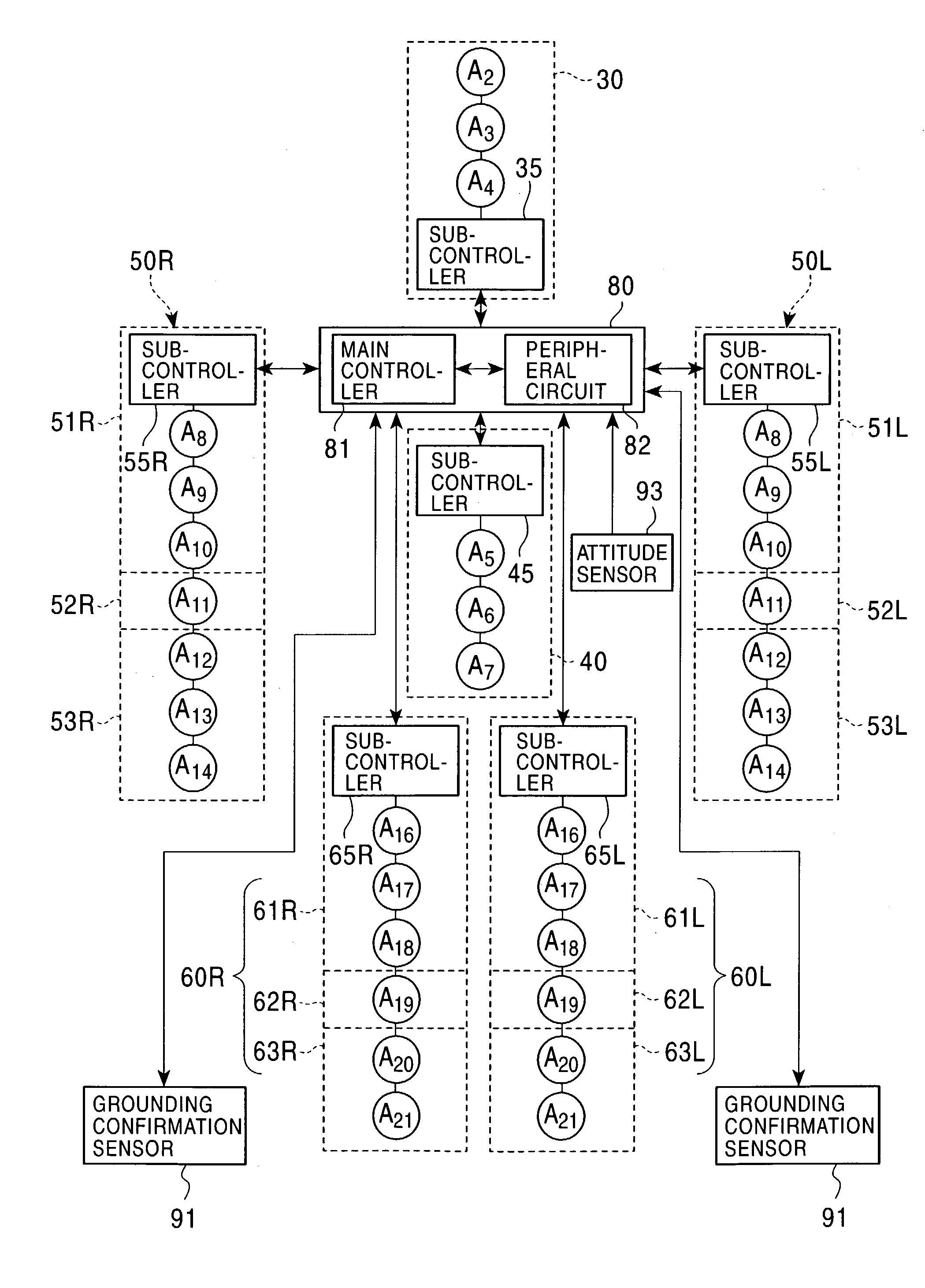
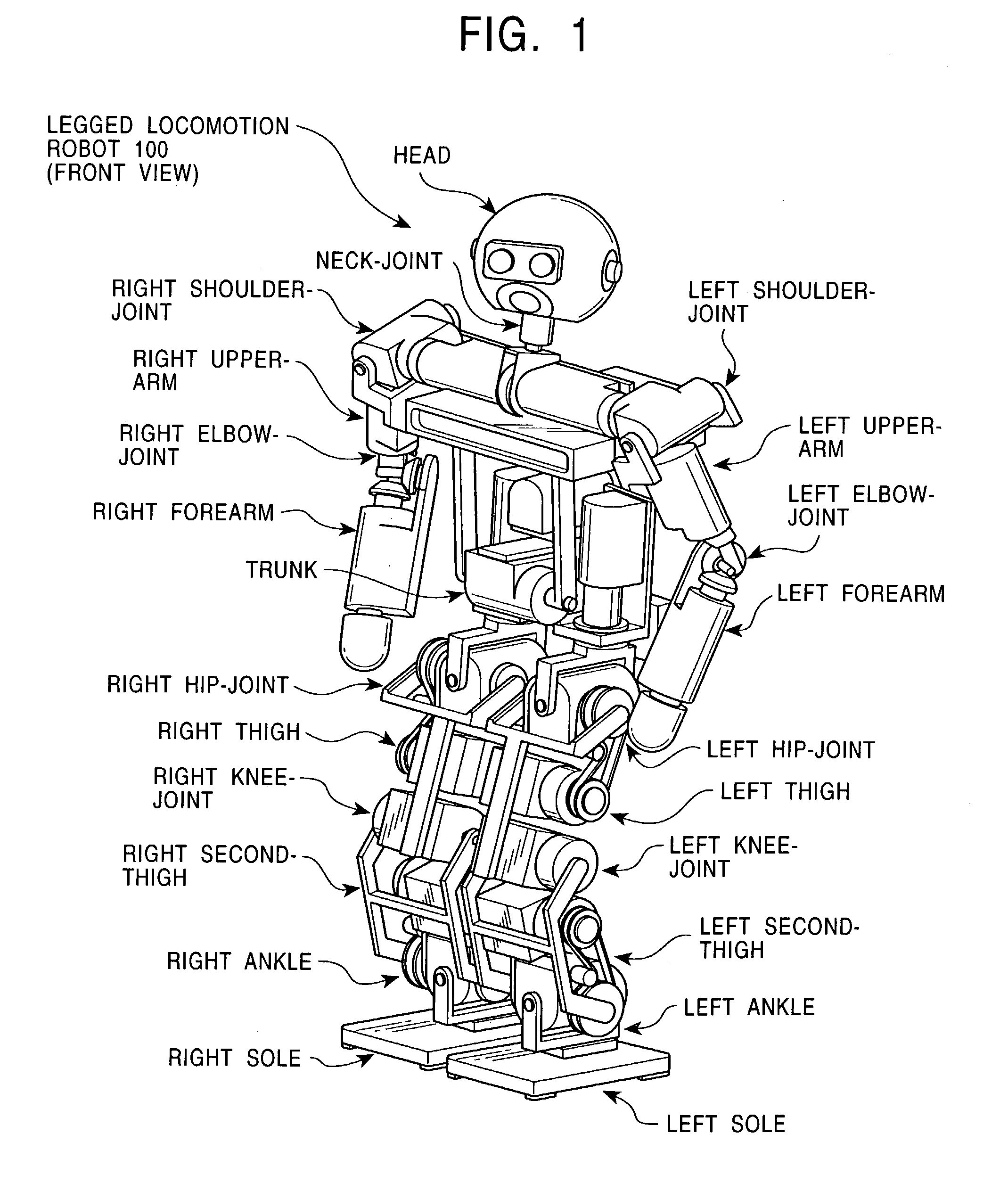
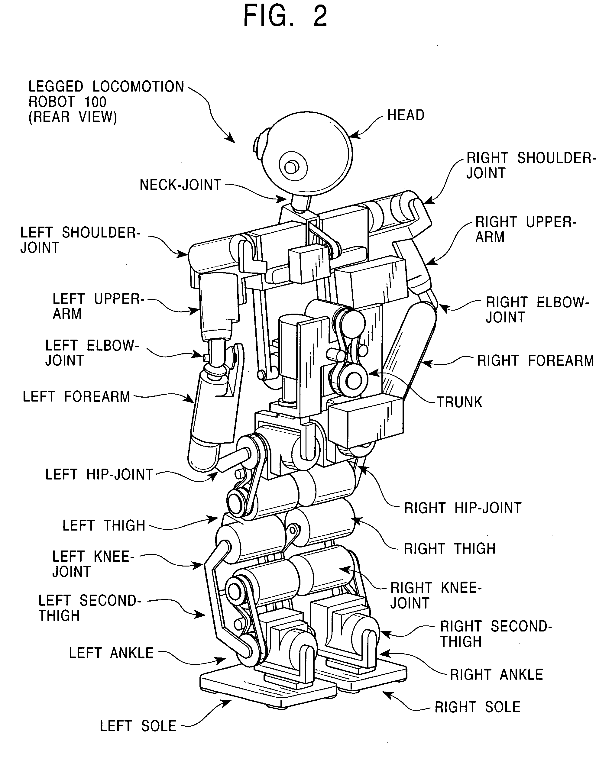
[0112] FIGS. 1 and 2 are respectively perspective front and rear views of a legged walking robot 100 according to an embodiment of the present invention. FIG. 3 is a schematic illustration of a multi-joints degrees-of-freedom configuration model that the legged walking robot 100 is provided with.

[0113] As shown in FIG. 3, the legged walking robot 100 has upper limbs including two arms and a head 1, lower limbs including two legs for achieving a locomotive motion, and a trunk connecting the upper limbs and the lower limbs.

[0114] A neck joint for supporting the head 1 has 3 degrees of freedom: i.e., a neck-joint yaw-axis 2, a neck-joint pitch-axis 3, and a neck-joint roll-axis 4.

[0115] Each arm has a shoulder-joint pitch-axis 8, a shoulder-joint roll-axis 9, an upper-arm yaw-axis 10, an elbow-joint pitch-axis 11, a forearm yaw-axis 12, a wrist-joint pitch-axis 13, a wrist-joint r...


PUM


Abstract

The present invention allows a robot to operate accurately while canceling an affect of pitch-axis, roll-axis, and yaw-axis moments, these moments being applied on the robot body during a leg-moving operation such as walking. First, by calculating a pitch-axis moment and/or a roll-axis moment generated on the robot body at a preset ZMP by set motions of upper limbs, a trunk, and lower limbs, motions of the lower limbs and the trunk for canceling the pitch-axis moment and/or the roll-axis moment are obtained. Then, by calculating a yaw-axis moment generated on the robot body lying at the preset ZMP by the calculated motions of the lower limbs and the trunk, a motion of the upper limbs for canceling the yaw-axis moment is obtained.

Description

[0001] The present invention relates to motion controllers and motion control methods for a realistic robot having a structure imitating a mechanism or a motion of a living body, and in particular to motion controllers and motion control methods for a legged walking robot having a structure imitating a mechanism or a motion of the likes of a human and an ape who walk erect.[0002] More particularly, the present invention relates to a motion controller and a motion control method for a legged walking robot which stably and accurately performs a leg-moving operation such as high-speed walking, and yet in particular to a motion controller and a motion control method for a legged walking robot which operates stably and accurately while canceling an affect of roll-axis, pitch-axis and yaw-axis moments applied on the robot body during a leg-moving operation.[0003] A mechanical apparatus performing a motion that imitates a human motion by using an electric or magnetic effect is called a ROB...

Claims


Application Information

Patent Timeline
IPC IPC(8): B25J9/18B62D57/032G06N3/00
CPCG06N3/008B62D57/032B25J5/00
Inventor KUROKI, YOSHIHIROISHIDA, TATSUZOYAMAGUCHI, JINICHI
Owner SONY CORP
Why Eureka
Try Eureka