Light guide plate having anti-reflection layer and a method of manufacturing the same

a technology of anti-reflection layer and light guide plate, which is applied in the direction of identification means, lighting and heating apparatus, instruments, etc., can solve the problems of low yield of vacuum deposition and sputtering methods, high manufacturing cost, and high cost, and achieve the effect of anti-reflection for all visible wavelengths

Inactive Publication Date: 2003-07-03
ALPS ALPINE CO LTD
View PDF1 Cites 16 Cited by
  • Summary
  • Abstract
  • Description
  • Claims
  • Application Information

AI Technical Summary

Problems solved by technology

One problem is that the vacuum deposition and sputtering methods have a low yield and a high manufacturing cost.
The high cost arises, in part, because these methods are processed in batch.
Since the anti-reflection effect is provided by a combination of reflective indices and layer thicknesses, it can be difficult to achieve an anti-reflection effect for all visible wavelengths.
Durability can also become problem since the above-described anti-reflection layer 117 is made of multiple layers.
Multiple layers are especially sus...

Method used


Image

  • Light guide plate having anti-reflection layer and a method of manufacturing the same
  • Light guide plate having anti-reflection layer and a method of manufacturing the same
  • Light guide plate having anti-reflection layer and a method of manufacturing the same

Examples


Embodiment Construction

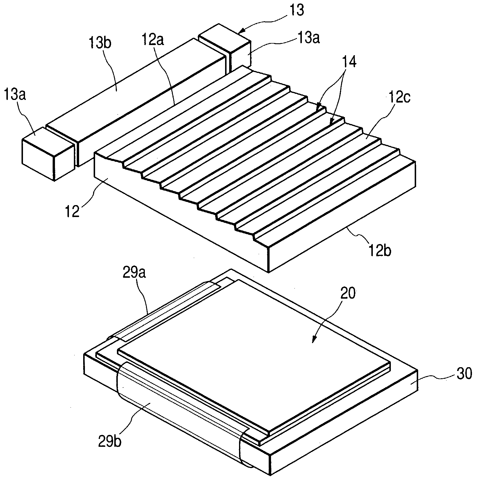
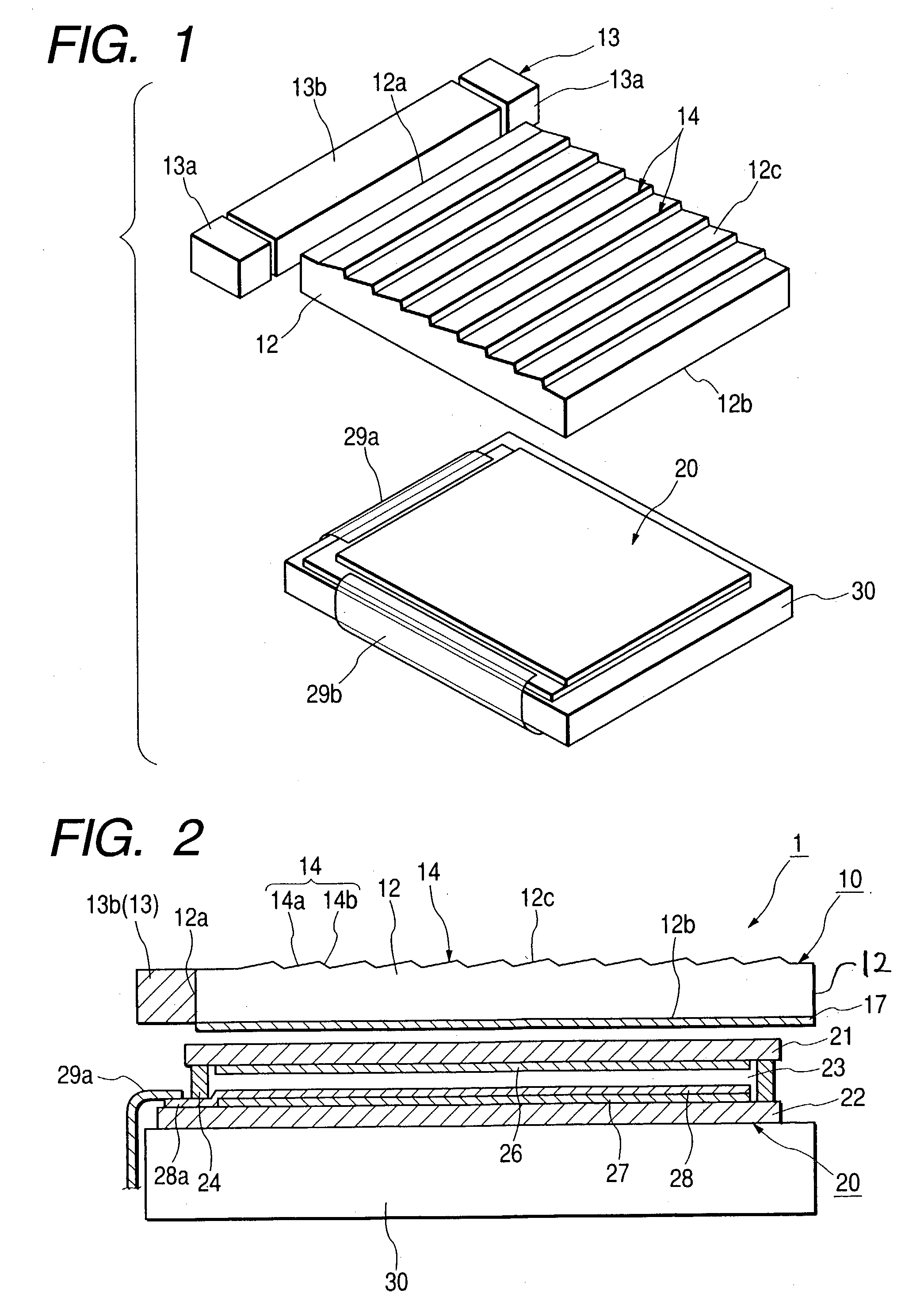
[0036] FIG. 1 is a perspective view of a liquid crystal display embodiment, and FIG. 2 is a sectional view of the liquid crystal display shown in FIG. 1. The liquid crystal display shown in FIGS. 1 and 2 is comprised of a reflection type liquid crystal panel 20 and a front light (illumination device or light source) 10 disposed near a front side.

[0037] The front light 10 is comprised of a transparent light guide plate 12 having a substantially flat plate like shape positioned adjacent to a light source 13. Preferably, the light source 13 is positioned near a side end face (light entering or receiving surface) 12a of the light guide plate 12. In this embodiment, the light guide plate 12 is made of an acrylic resin or polycarbonate-type resin, although other materials can also be used. The bottom side of the light guide plate 12 shown in FIG. 2 comprises an exit surface 12b where illumination from the front light 10 exits.

[0038] Preferably, a prism-like feature having a sectional view...


PUM

PropertyMeasurementUnit
Lightaaaaaaaaaa

Abstract

A light guide plate includes a light guide positioned to receive light from a light source at a side end face. The light guide includes an exit surface that conveys light from the guide plate. Preferably, the exit surface has an anti-reflection layer having microscopic recesses or projections arranged in a lattice.

Description

[0001] 1. Field of the Invention[0002] The present invention relates to an illumination device, and more particularly, to an illumination device disposed near a side of a liquid crystal panel.[0003] 2. Related Art[0004] Illumination devices also known as front lights are positioned on a front side of a reflection type liquid crystal display. The front lights are positioned above a viewer's side of a liquid crystal panel to illuminate a liquid crystal panel.[0005] FIG. 12 is a sectional view of a liquid crystal display 100 having a front light 110 positioned on a front side of a liquid crystal panel 120. In the illustrated liquid crystal panel 120, a liquid crystal layer 123 secured by a sealant 124 is positioned between a top substrate 121 and a bottom substrate 122. A liquid crystal control layer 126 is positioned on an inner surface of the top substrate 121. A reflection layer 127 having a high reflectance is positioned below a liquid crystal control layer 128.[0006] As shown, the...

Claims


Application Information

Patent Timeline
IPC IPC(8): F21S2/00G02B6/00F21V8/00F21Y115/10G02F1/13357G09F9/00
CPCG02B1/11G02F1/133615G02B6/0038G02B6/0036G02F1/1335
Inventor ISHITAKA, YOSHIHIKO
Owner ALPS ALPINE CO LTD
Why Eureka
Try Eureka