Image graphic system comprising a highly tacky adhesive and method for using same

a graphic system and adhesive technology, applied in the field of image graphic system comprising a highly tacky adhesive and method for using same, can solve the problems of low and limited low adhesive holding power, and inability to clean up to restore original holding power of adhesive, etc., to achieve easy removal and reapplication, and sufficient adhesion force

Inactive Publication Date: 2003-07-10
3M INNOVATIVE PROPERTIES CO
View PDF47 Cites 11 Cited by
  • Summary
  • Abstract
  • Description
  • Claims
  • Application Information

AI Technical Summary

Benefits of technology

0087] An advantage of the present invention is that the system allows the t adhesive and film to be separate components, and thus optimized for a specific application. For adhesive carrier 12, the pressure sensitive adhesive chosen for surface 22 can be designed for optimum adhesion to the substrate 14, while the adhesive chosen for highly tacky adhesive surface 26 can be very tacky indiscriminately or very tacky discriminately depending on the duration and environment of usage.
0088] The system 10 could be seen to have one limitation, namely that the system 10 in certain embodiments requires two applications; first adhesive carrier 12 to the substrate 14, and second image carrier 16 to adhesive carrier 12. While having to do two applications is a disadvantage, this is mitigated by the following factors: first, each of the applications is-easier. If the adhesive carrier 12 is misaligned during application, the material can be trimmed square and to the proper size. The highly tacky adhesive has sufficient adhesion force as to tear 20 lb. bond paper under 90 degree peel test conditions. Wrinkles can be cut out and replaced. Second, the lower adhesion of the image carrier 16 to adhesive carrier 12 (relative to the adhesion of adhesive carrier 12 to substrate 14) allows for easy, bubble-free application of the graphic, and easy removal and reapplication. Consequently, this step is very fast. Third, the system can be effectively used for image graphics where the adhesive carrier 12 is applied once, and the image carrier(s) 16 is applied and removed numerous times as the graphic is changed. Thus, the two applications are only done for the first time a graphic is placed. After that only an image carrier 16 is applied. Fourth, since the removal of the graphic image is easy and controlled, the time for changing graphics is greatly reduced. Thus, the system's time advantage is realized as the number of changes in the graphic increases.
0089] Another advantage of the system of the present invention over conventional image graphics where the imaged film is adhesive-backed is that system 10 has less waste and potentially lower cost for a changeable graphics system. In a conventional adhesive-coated graphic, a customer must buy three components for each application: a graphic film, a pressure sensitive adhesive and a high quality liner. The liner is thrown away during application, and the pressure sensitive adhesive is disposed of when removing the graphic. In system 10, adhesive carrier 12 is supplied with a liner that also must be thrown a during application. However, the liner for adhesive carrier 12 is much less costly because the adhesive carrier 12 does not go through the print process, where a high quality liner may be needed for dimensional stability. The dual layer construction of the adhesive carrier 12 can be seen as consuming slightly more materials than traditional PSA on a conventional graphic only when using the system as a one-time application system. The material savings for the total system 10 occur when changing graphics; only the image carrier 16, without adhesive and without liner, is disposed to be replaced by a new image carrier, without adhesive and without liner. The adhesive is recycled in place. Further, since a customer only needs to buy another image carrier 16 for subsequent graphics, money is saved or can be used to purchase a better quality film or higher resolution image graphics.
0090] In comparison to mechanically fastened graphics, the system 10 has an important and advantageous attribute: the system 10 preferably has the thin caliper and conformability of a conventional pressure sensitive adhesive film graphic. In contrast, mechanically fastened graphics have the disadvantage of being relatively thick, bulky, and difficult to handle. Graphics that use a frame or rigid substrate are limited to flat applications. Even micromechanical bonding systems such as hook and loop are still an order of magnitude thicker than a pressure sensitive adhesive graphic. Thus, mechanically fastened graphics can not achieve in most applications the desired "painted-on" look of an adhered graphic. System 10 preferably has the advantage of retaining the thin caliper that gives the "painted-on" look of the high quality pressure sensitive adhesive graphics. Preferably the total image graphic is less than 20 mils thick. More preferably, the total image graphic is less than 10 mils thick.
0091] A second advantage of system 10 over graphics such as hook and loop systems or gross mechanical fasteners such as staples is that the system 10 can preferably be used in back-lit graphic applications. Mechanically fastened graphics as described above do not perform well in this application because they a-e fairly expensive, they are too thick and do not let light pass through, or the construction is of intermittent density (i.e.: hook and loop) so that the light transmission is uneven. Preferred embodiments of system 10 have the advantage in that both layers can give uniform light transmission.
0109] Adhesion at interfaces changes over time. Therefore at about 14 days of dwell time, the percentage ranges from about 10 to about,90 in order to provide predictable performance at the respective interfaces, based on choices of adhesives and how such adhesives interact with the surfaces such adhesive contact over time.

Problems solved by technology

First, the manufacture of double-sided sheets frequently employ a release liner spirally wound with the sheet itself.
The repositionability of notes on the major surface means that the adhesive is designed to have a low and limited amount of holding power.
Further, as the exposed major surface of adhesive becomes contaminated with dirt, oils etc., the adhesive can not be cleaned to restore its original holding power.
The substrate to which cling vinyl image graphics bond is limited in adhesion to extremely smooth surfaces such as glass, which makes a bond that has very low adhesive holding power.
Image graphics using pressure sensitive adhesive surfaces, while extremely versatile, can encounter a number of limitations.
First is that the inherent tackiness of the adhesive causes problems in applying the graphic smoothly and evenly to the surface.
In the worst case, the graphic can be damaged removing it, which means the graphic needs to be replaced with a new graphic, a considerable expense.
Improvements such as contained in Controltac.TM. branded films sold by 3M have special adhesives to limit the initial adhesion, and thus allow limited repositionability.
While the use of special adhesive formulations definitely provides assistance in the initial placement of the graphics, these improved adhesives are not designed specifically for problems such as wrinkles that show up after the major portion of a graphic has been applied.
However, this approach ends up causing a second limitation in image graphics using pressure sensitive adhesives: the adhesive must bond acceptably to numerous substrates for the intended application.
Moreover, when an adhesive is formulated to be removable, the situation worsens, because the adhesive can have three possible levels of adhesion: too high, too low or acceptable.
Therefore, pressure sensitive adhesives are o-;ten formulated with a compromise in performance that all too often is not optimum for a particular application.
This results in more logistical problems for the customer.
Another issue facing films that have an image on one major surface and a field of adhesive on the opposing major surface is the care during storage and placement so as not to contaminate the adhesive with dirt or other effects that diminish the intended adhesiveness.

Method used


Image

  • Image graphic system comprising a highly tacky adhesive and method for using same
  • Image graphic system comprising a highly tacky adhesive and method for using same

Examples


example 1

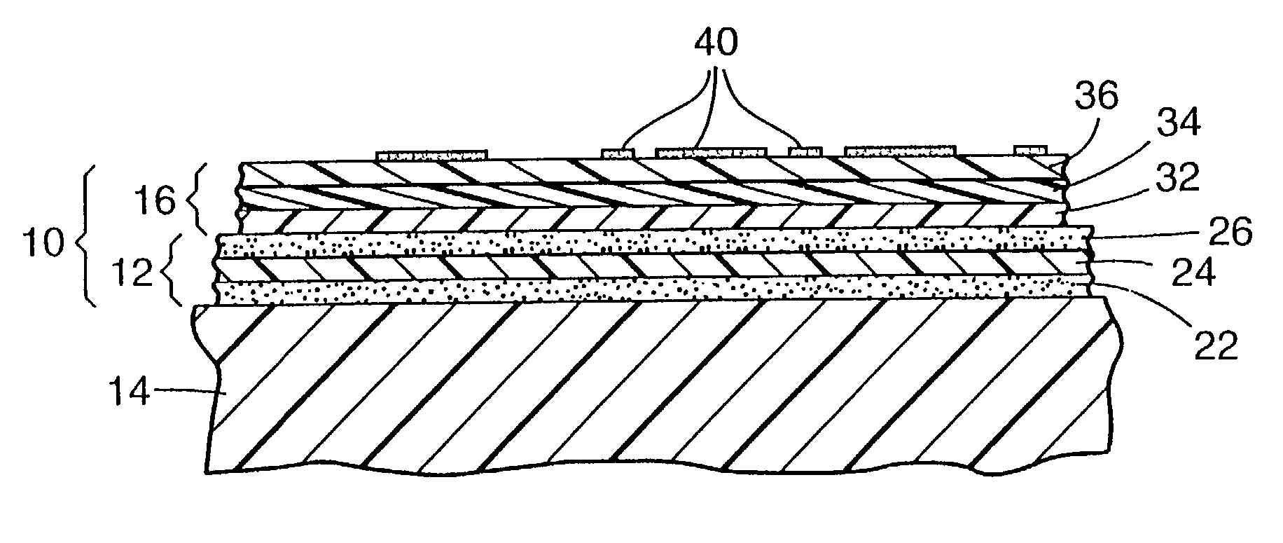
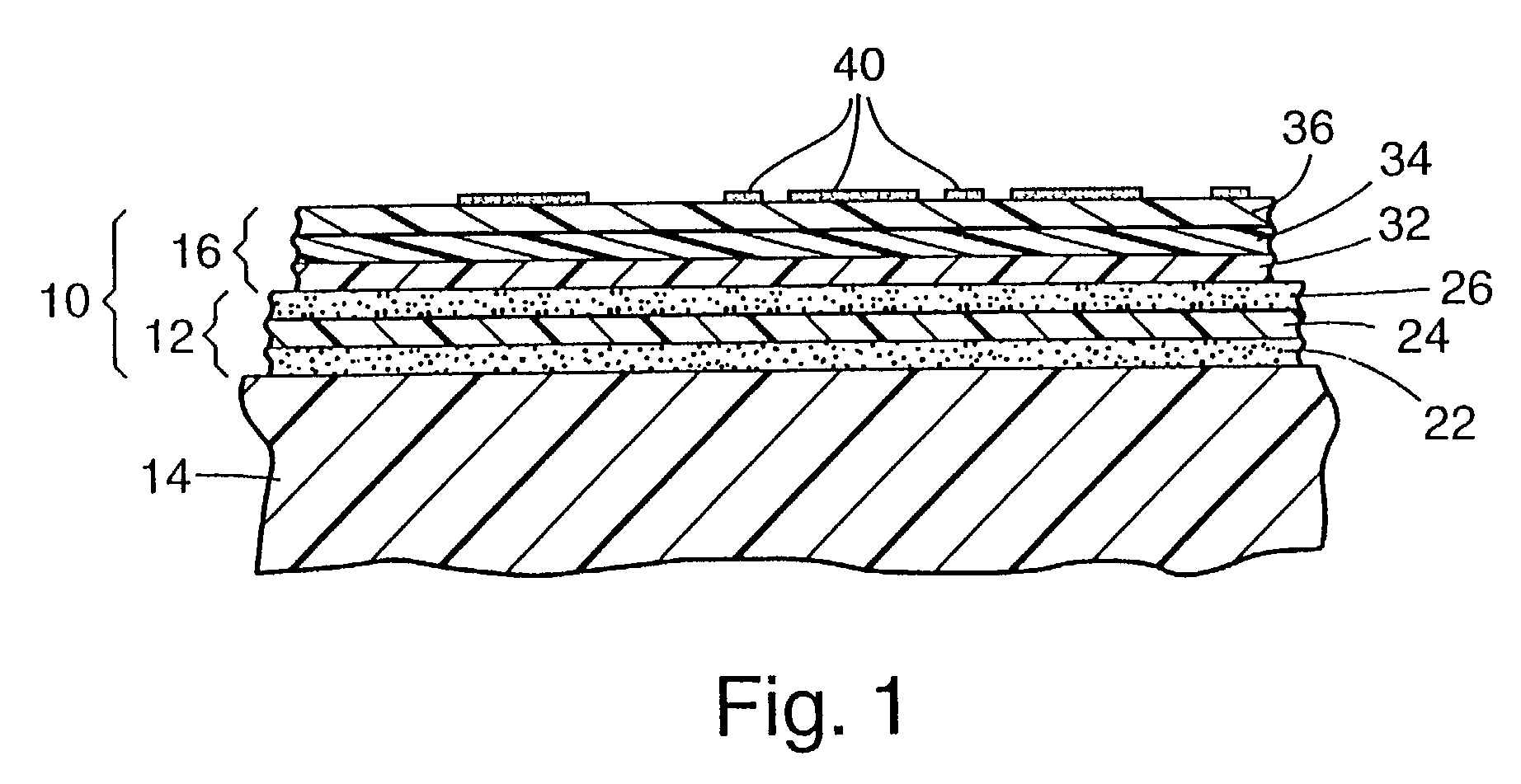
[0175] A painted sheet metal sign board designed for the display of advertising graphics was chosen as a substrate.

[0176] A DIN A4 (21.0 cm.times.29.7 cm) sheet of double-coated adhesive having a high tack acrylic PSA on one side and a low tack acrylic PSA on the other side, available as Tape No. 9415 High Tack / Low Tack Double-Coated Tape from 3M Company, St. Paul, Minn., USA, was laminated to cover a portion one of the two surfaces of the advertising board. The sheet, available in roll form with a single liner on the low adhesion side, was first unrolled and cut to the appropriate size. A second liner was then adhered to the high adhesion side. The liner was then removed from the low adhesion side and the adhesive adhered to the painted steel substrate using a rubber-coated roller.

[0177] An image graphic was prepared by writing a message by hand using a felt-tipped marking pen on a siliconized paper, available as 75 g Release PMC (standard low release level) from Lohjan Paperi (Fin...

example 2

[0181] Example 1 was repeated with the exception that the siliconized-paper image carrier was imaged on the non-siliconized side using a photocopier. Essentially the same results were obtained as in Example 1.

example 3

[0182] Example 1 was repeated with the exception that the siliconized-paper image carrier was imaged on the non-siliconized side using a laser printer. Essentially the same results were obtained as in Example 1.


PUM

PropertyMeasurementUnit
surface energyaaaaaaaaaa
anglesaaaaaaaaaa
anglesaaaaaaaaaa

Abstract

An adhesively mountable image using a highly tacky reusable adhesive surface is provided. The image carrier is removable from the adhesive carrier, and it subsequent image carrier may be releasably bound to the same adhesive carrier. Kits for this system are also provided.

Description

[0001] This invention relates to combined adhesive / substrate systems for placement and removal of image graphics.BACKGROUND OF INVENTION[0002] Image graphics are omnipresent in modern life. Images and data that warn, educate, entertain, advertise, etc. are applied on a variety of interior and exterior, vertical and horizontal surfaces. Nonlimiting examples of image graphics range from posters that advertise the arrival of a new movie to warning signs near the edges of stairways.[0003] Readily replaceable image graphics are needed for those occasions when the length of time the graphic needs to remain at the intended location is limited to a short duration. Often with a replacement image graphic substituting for the image graphic to be removed. An example of an expected replacement image graphic is the movie poster identified above.[0004] Readily replaceable image graphics require both the "staying power" when placed on the horizontal or vertical surface and the "leaving ease" when t...

Claims


Application Information

Patent Timeline
Patent Type & Authority Applications(United States)
IPC IPC(8): A47G1/17G09F7/12
CPCG09F7/12A47G1/17
Inventor KRECKEL, KARL WERNERKUESTER, WILHELMMUELLER, BRUNO
Owner 3M INNOVATIVE PROPERTIES CO
Why Eureka
Try Eureka