Methods for positioning a print integrity image capture device

a capture device and print integrity technology, applied in typewriters, instruments, visual presentations, etc., can solve the problems of reducing the productivity of the operator and printing process, affecting the efficiency of the printing process, and not being practicable or desirable to place a print integrity identifier

Inactive Publication Date: 2003-07-17
XEROX CORP
View PDF11 Cites 13 Cited by
  • Summary
  • Abstract
  • Description
  • Claims
  • Application Information

AI Technical Summary

Benefits of technology

[0012] By automatically adjusting the image capture location for each page within a document or from document to document, the print operator's workflow may be carried out smoothly, with a decrease in disruptions. Set-up time between print jobs may also be reduced, ultimately reducing the operational cost to a print shop.
[0013] A further advantage of the systems and methods of this invention is that a page designer for a particular document no longer needs to be concerned with the location of the integrity identifier. Thus, the page design may be varied from page to page for aesthetic or other reasons. This automated process will also increase reliability, in that the need for a print operator to become involved in the lengthy and time-consuming manual process of setting up and adjusting the data integrity system may be reduced, or possibly eliminated. Automatically identifying scanned areas may also improve scanning accuracy and thus add to an increased system-wide reliability in the variable data printing process.

Problems solved by technology

In this situation, it may not be practical or desirable to place a print integrity identifier, such as a bar code or a glyph, consistently in the same space on the printed page.
This manual process can be lengthy and time-consuming, thus reducing the productivity of the operator and printing process.
Additionally, because the camera location is adjusted manually, there is the possibility of error in positioning the camera in reference to the print integrity identifier.
If the camera has not been adequately aligned with the print integrity identifier, complications or errors could result in the system.
Because this process is also manual, it can also be time-consuming and is subject to operator error.
Further complexities can arise when multiple identifiers occur on each page.
The manual process of adjusting the image capture device disrupts the print operator's workflow and also increases set-up time between print jobs.
These disruptions and increases in set-up time between print jobs ultimately lead to increased operational costs to a print shop.

Method used


Image

  • Methods for positioning a print integrity image capture device
  • Methods for positioning a print integrity image capture device
  • Methods for positioning a print integrity image capture device

Examples


Embodiment Construction

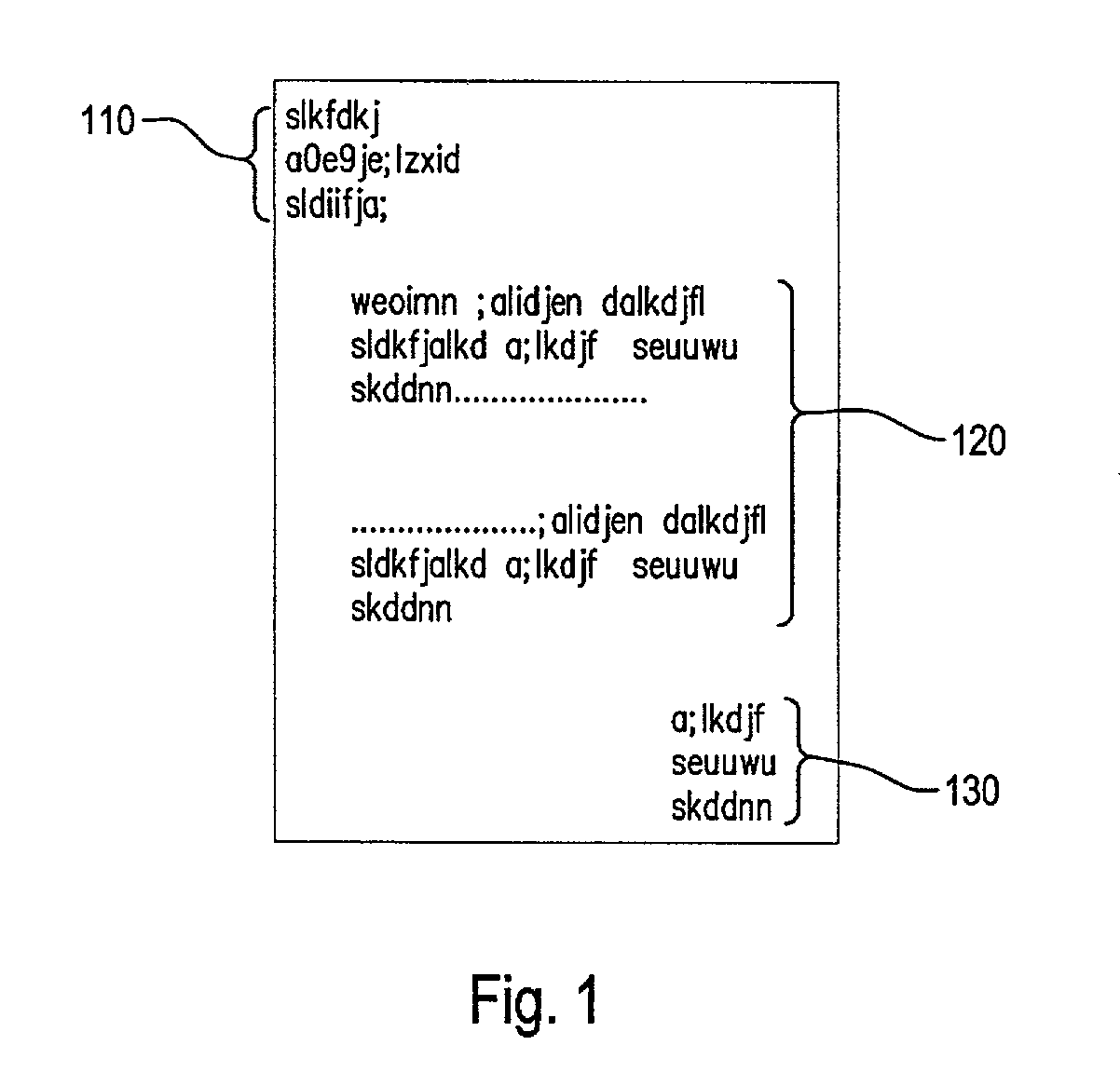
[0021] FIG. 1 illustrates a typical page 100 of a document that is used with the systems and methods of this invention. The page 100 has a variable address portion 110 which may vary in size and typically may be located towards the top of the page. Below the variable address portion 110 is a variable text portion 120. A print integrity identity portion 130 is located somewhere on the page 100. This variable text portion 120 may vary according to content and also according to the type of document that is being produced. For example, in the case of financial transactions like credit card bills or bank statements, the variable text portion may vary according to the activity in a particular account and according to each individual customer.

[0022] In this case, it may not be practical or desirable to have the print integrity identifier 130 in the same location from document to document, or from page to page. Instead, it may be more desirable to be able to locate the print integrity ident...


PUM


Abstract

A method for positioning a print integrity image capture device comprises the steps of creating electronic document data; adding print integrity markings to the electronic document data; sending the electronic document data to a raster image processor; determining the location of integrity markings for a tangible print of electronic document data; automatically adjusting an image capture device location based on integrity marking location information; providing necessary scheduling information to a feeding device and / or a sorting device; printing a tangible print of electronic document data; scanning a tangible print of electronic document data based on a determined image capture location; analyzing an image to determine which integrity marking is located on the tangible print of electronic document data; relaying an integrity marking number to a production management algorithm; determining whether all tangible prints of electronic document data have been printed; and determining whether all documents have been printed.

Description

[0001] 1. Field of Invention[0002] This invention relates to print production processes and positioning print integrity image capture devices based on the locations of print identifiers.[0003] 2. Description of Related Art[0004] In current print production processes, when printing certain documents containing variable data, such as financial transactions, it is essential that verification be performed on the printed output document. Typically, a print integrity identifier, such as a bar code or glyph, may be printed on each page of a document. An imaging device, such as a camera or scanner, may then capture the identifier on the printed page. The captured image is fed to a decoding algorithm, which analyzes the image and determines which identifier is present on the page. This information may then be used to determine which pages of a document have or have not been printed within a variable data job. Because a print job may be composed of many individual documents, the information m...

Claims


Application Information

Patent Timeline
Patent Type & Authority Applications(United States)
IPC IPC(8): H04N1/32
CPCH04N2201/3235H04N1/32133
Inventor ROBINSON, DAVID C.AXELROD, MICHAEL
Owner XEROX CORP
Why Eureka
Try Eureka