Optical modulators and a method for modulating light

a technology of optical modulators and light, applied in the field of optical modulators, can solve the problems of low light intensity of off-mode received light and unstable for realizing efficient and stable control of the operational poin

Inactive Publication Date: 2003-07-24
NGK INSULATORS LTD
View PDF6 Cites 96 Cited by
  • Summary
  • Abstract
  • Description
  • Claims
  • Application Information

AI Technical Summary

Problems solved by technology

The light of off-mode is, however, propagated in the substrate, reflected at the interface between the substrate and air and thus scattered.
The light intensity of the received light of off-mode is thus low and unstable for realizing efficient and stable control of the operational point.

Method used


Image

  • Optical modulators and a method for modulating light
  • Optical modulators and a method for modulating light
  • Optical modulators and a method for modulating light

Examples


Embodiment Construction

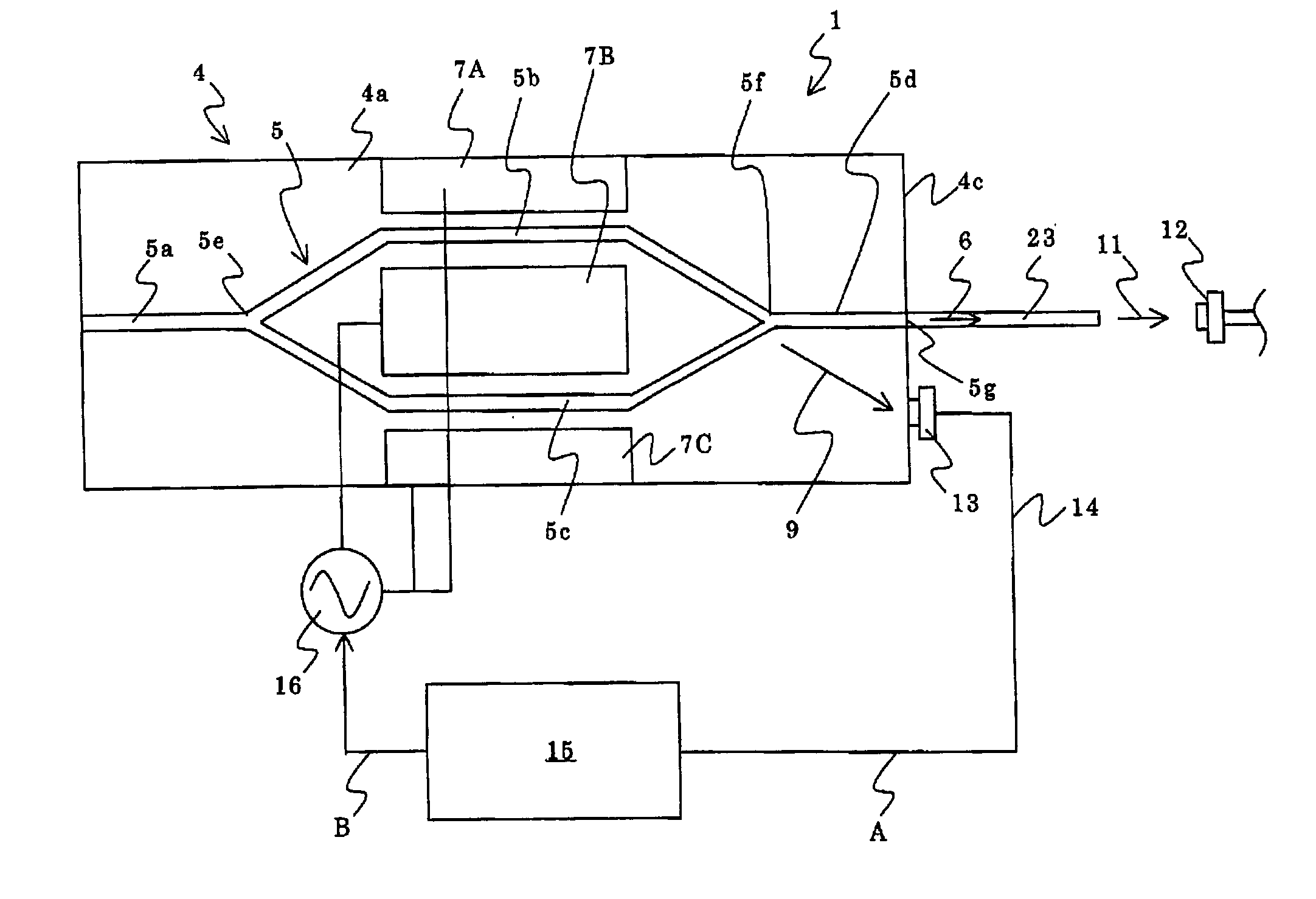
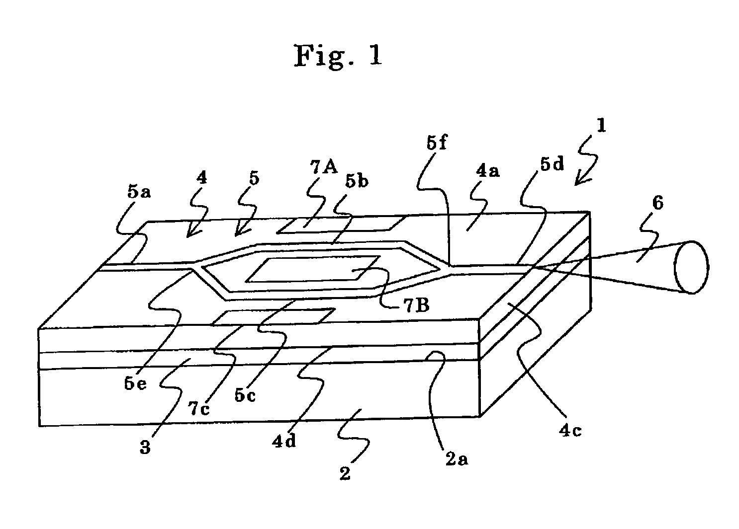
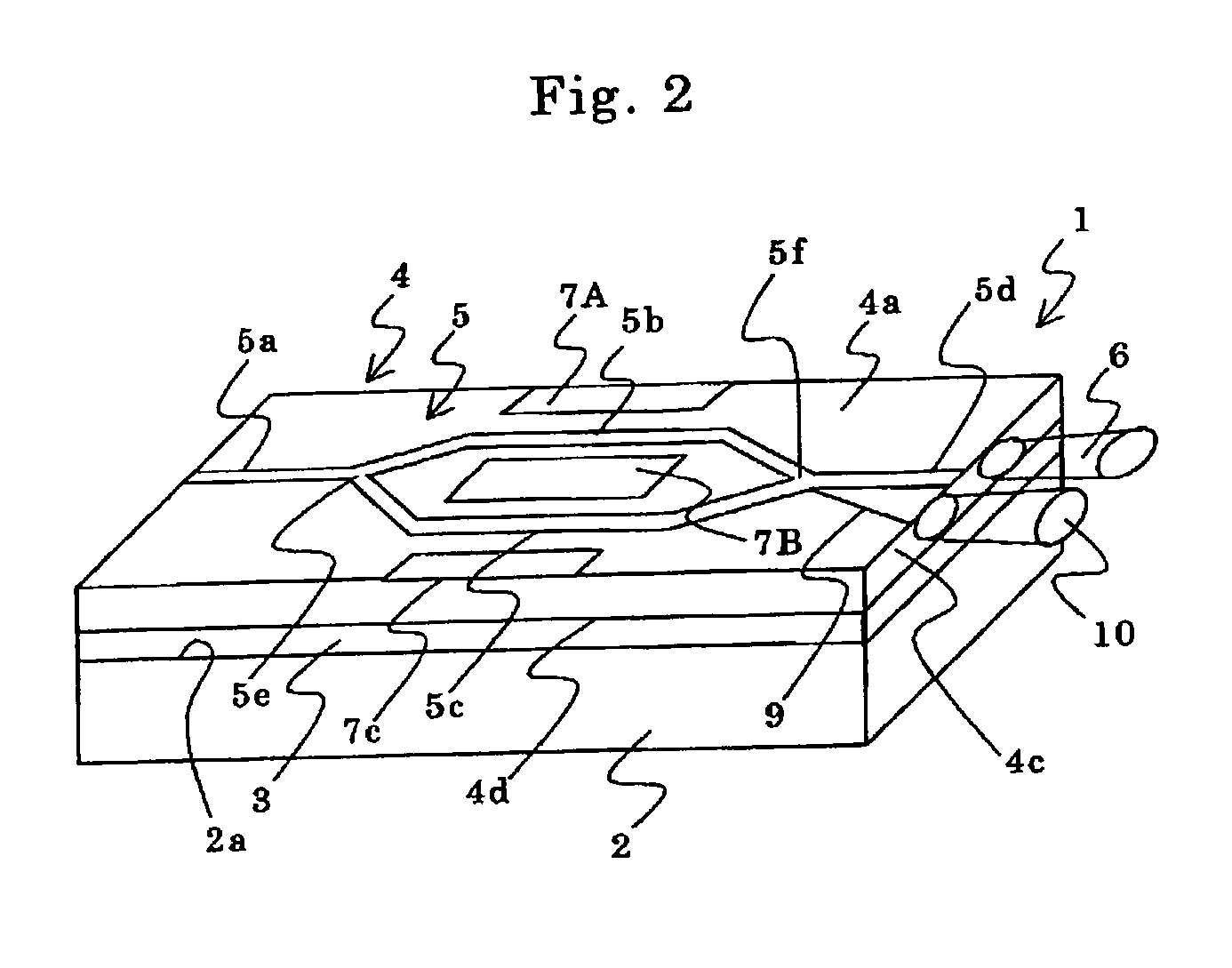
[0028] The present invention will be further described, referring to FIGS. 1 to 3. An optical modulating device 1 according to the present embodiment has a supporting substrate 2, a slab type optical waveguide 4 and an adhesive layer 3 joining a surface 2a of the substrate 2 and a bottom 4d of the waveguide 4. The slab optical waveguide 4 is composed of a flat plate made of a material having a refractive index higher than that of the adhesive layer 3. A three-dimensional optical waveguide 5 of Mach-Zehnder type and modulating electrodes 7A, 7B and 7C are formed on the side of the surface 4a of the flat plate 4. The waveguide 5 has an input portion 5a, a pair of branched portions 5b, 5c and an output portion 5d. 5e represents a splitting point and 5f a recombining portion. A method for modulating light propagating in the waveguide 5 and detailed construction of the electrodes are known and their explanation will be omitted

[0029] As shown in FIGS. 1 and 3, a signal light 6 is emitted ...


PUM

PropertyMeasurementUnit
refractive indexaaaaaaaaaa
thicknessaaaaaaaaaa
thicknessaaaaaaaaaa

Abstract

An optical modulator modulates light propagating in a three-dimensional optical waveguide 5 by applying a voltage on the waveguide. The modulator has a three dimensional optical waveguide 5 having at least a pair of branched portions 5b, 5c and a recombining portion 5f of the branched portions 5c, 5d and radiating light of off-mode, and a slab optical waveguide 4 guiding the light of off-mode. The modulator also has modulating electrodes 7A, 7B, 7C for applying a signal voltage and a direct current bias on the waveguide 5 to modulate light propagating in the waveguide 5. The modulator further has a photo detector 13 for detecting light radiated from the slab optical waveguide 4, and a controlling unit 15 for varying the direct current bias based on an output from the photo detector 13 so as to control the operational point of the modulator. According to the modulator, the operational point may be controlled with improved efficiency and stability.

Description

[0001] This application claims the benefit of Japanese Patent Application P2001-351142 filed on Nov. 16, 2001, the entirety of which is incorporated by reference.[0002] 1. Field of the Invention[0003] The present invention relates to an optical modulator.[0004] 2. Related Art Statement[0005] It has been noted a travelling-wave type high speed optical modulator using so-called Mach-Zehnder type optical waveguide. According to this type of optical modulator, light is propagated in a pair of branched waveguide portions, respectively, so that the outputs from the branched waveguides are recombined at a recombining portion. The shift of the operational point or DC drift may occur due to a cause such as a temperature difference between the branched waveguide portions[0006] Several methods have been proposed to control the shift of the operational point or DC drift. Representatively, Japanese patent publication P3-145, 623A discloses a method for utilizing light of substrate radiation-mode...

Claims


Application Information

Patent Timeline
Patent Type & Authority Applications(United States)
IPC IPC(8): G02F1/01G02F1/225
CPCG02F1/0123G02F1/225G02F2203/21G02F2201/503G02F2202/42G02F1/2255
Inventor KONDO, ATSUOMITOMI, OSAMUKONDO, JUNGOAOKI, KENJI
Owner NGK INSULATORS LTD
Why Eureka
Try Eureka