Convertible blood clot filter

a clot filter and vena cava technology, applied in the field of clot filter, can solve the problems of affecting the patient's blood flow, causing bleeding complications, and causing the rupture of the vena cava, and causing the patient to undergo several risks

Inactive Publication Date: 2003-07-24
ANGIODYNAMICS INC
View PDF11 Cites 93 Cited by
  • Summary
  • Abstract
  • Description
  • Claims
  • Application Information

AI Technical Summary

Problems solved by technology

However, anticoagulant therapy carries the risk of bleeding complications.
If an attempt is made to remove the filter after this time point, severe damage may occur resulting in laceration or rupture of the vena cava, or at the very least, a focal disruption of the endothelial lining which may predispose to caval stenosis, thrombosis (clot formation) or occlusion.
Since the permanent blood clot filters are left in the body for the lifetime of the patient, the patient undergoes several risks that continue throughout the person's lifetime.
These problems can occur because the blood clot filter is directly in the blood stream and continually filtering the blood clots throughout the lifetime of the patient.
Thrombotic occlusion and filter embolization can occur when a gradual buildup of blood clots forms in or around the filter due to the continuous filtering.
Filter migration and filter fragmentation can occur because of the constant impact between the blood filter and the flowing blood can move the filter or break the structure of the filter.
However, the situations in which temporary blood clot filters are used are limited.
In addition to the limited amount of time that it can remain in the vena cava, the catheter-based design has the draw back of infectious complications at the entry site.
These patients will receive a permanent filter and be unnecessarily subjected to the lifelong risks associated with permanent blood clot filters.

Method used


Image

  • Convertible blood clot filter
  • Convertible blood clot filter
  • Convertible blood clot filter

Examples


second embodiment

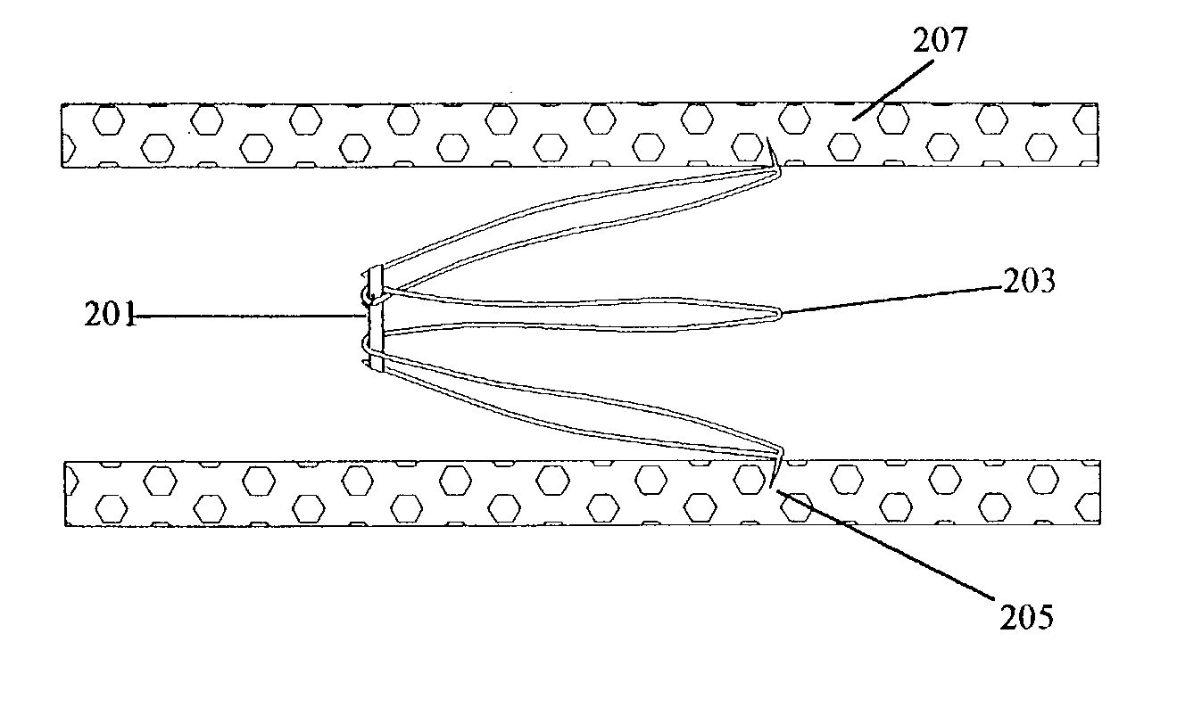
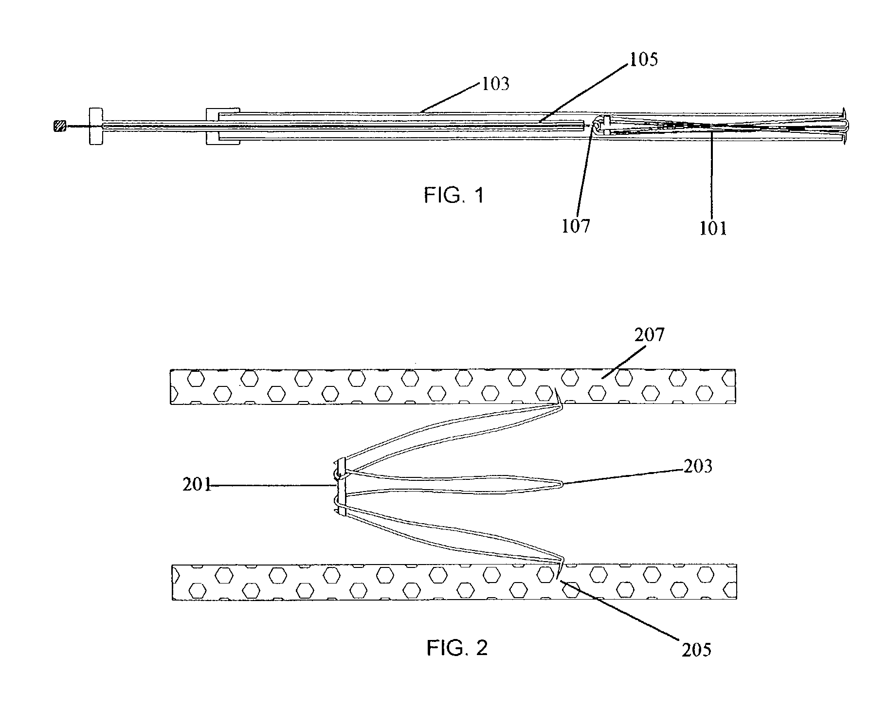
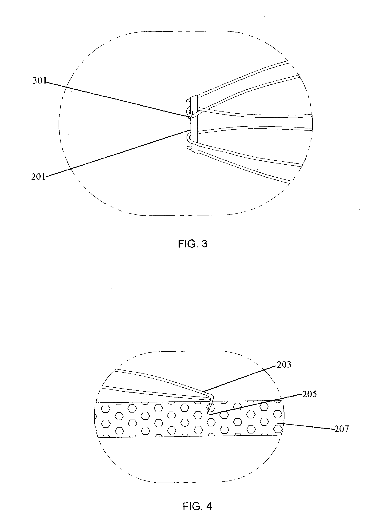
[0054] FIGS. 9A-9B depict the present invention. Filter 101 is presented in its deployed form. Ring 201 retains the narrow end of the filter 101 in its conical shape and is intertwined with the wire of the filter such that the ring will not be dislodged from the filter body. Ring 201 is shown as a tied suture. Tie 301, however, is not connected to the filter 101. Not connecting the ring 201 to the filter 101 via tie 301 allows the ring 201 to be completely removed after the ring 201 has been broken.

[0055] FIGS. 10A and 10B depict a modification of the second embodiment that uses a unitary ring 201, rather than a tied suture, to contain the conical end of the filter 101. The unitary ring 201 is slid over the barbed end by weaving it over and under alternating leg sets. The ring is slid fully to the opposite end where it remains in position holding the conical end of the filter in the constrained position. The advantage of this simple unitary ring is there is no knot that can be prone...

third embodiment

[0057] FIGS. 12 and 13 depict the present invention. Filter 101 is composed of two pieces, the base section 1201 and the filter section 1203. The base section 1201 is cylindrical in shape and completely lines the walls of the cava vena. Barbed anchors hold the base section in place against the caval wall.

[0058] The filter section 1203 is shaped into a cone and has a hooked portion 1205 at the end of each leg 1203. This hooked portion 1205 will engage with corresponding bends in the wire of the base section 1201. The blood flow will push the hooked portions 1205 against the bent wire to hold the filter section 1203 connected to the base section 1201. At the apex of the cone, a disengaging hook 1207 is placed.

[0059] To disengage the filter section 1203 from the base section 1201, a removal device 1301 is inserted. The removal device 1301 can have a hook 1303 contained within an outer tube 1305. The removal device is maneuvered over the disengaging hook 1207 of the conical filter secti...

fourth embodiment

[0060] FIGS. 14 and 15 depict the present invention. Similar to the third embodiment, the filter 101 is composed of two pieces, the base section 1401 and the filter section 1403. Legs 1405, however, contain weakened sections that are predisposed to be broken when desired. The weakened sections can be designed to be broken by the application of a low voltage electrical current or be a physically weaker substance. FIG. 15 depicts the removal device to be used for the fourth embodiment in which hook 1503 engages disengaging hook 1407 and filter section 1403 breaks off at predetermined weakened sections 1409. Once completely broken off, the filter section 1403 can be retracted into the removal device and extracted from the patient.

[0061] FIGS. 16 and 17 depict yet another embodiment of the present invention. Filter 101 is composed of a single wire structure and shaped in the form of a cone to filter the blood stream. At the narrow end of the filter, the apex of each return bend is shape...


PUM


Abstract

A vena cava blood clot filter is described that is attached to the walls of the vena cava by barbed anchors. In its filtering state, the filter is cone shaped which causes the blood to be filtered. The cone shape is formed by an appropriate restraining mechanism. When it is desired to stop filtering, the restraining mechanism is released and the filter takes a cylindrical shape. The cylindrical shaped filter will then line the vena cava wall and cease filtration of the blood.

Description

[0001] 1. Field of Invention[0002] The following invention relates to a clot filter and more specifically to a convertible vena cava blood clot filter.[0003] 2. Description of the Related Art[0004] Vena cava blood clot filters are generally placed in the inferior vena cava, introduced either through the femoral or jugular vein. These filters trap blood clots that have arisen from the peripheral veins and that travel through the vena cava. By trapping the blood clots, the filter prevents the clots from lodging in the pulmonary bed, which can lead to a condition known as pulmonary embolus.[0005] Pulmonary embolus (PE) has long been recognized as a major health care concern. Untreated PE is associated with a high mortality rate, widely held to be approximately 30%, although the exact rate is unknown. Symptomatic PE, however, represents only one manifestation of a more protean disorder, venous thromboembolic disease (VTD), which includes both deep venous thrombosis (DVT) and PE. Underst...

Claims


Application Information

Patent Timeline
Patent Type & Authority Applications(United States)
IPC IPC(8): A61F2/01
CPCA61F2/01A61F2230/0067A61F2230/005A61F2002/016A61B17/221
Inventor PATEL, NILESH H.MORESCO, KENNETH P.APPLING, WILLIAM M.
Owner ANGIODYNAMICS INC
Why Eureka
Try Eureka