Electromagnetic valve for controlling an injection valve of an internal combustion engine

a technology of electromagnetism and injection valve, which is applied in the direction of fuel injecting pumps, machine/engines, operating means/releasing devices of valves, etc., can solve the problems of armature bounce, impairing the control of injection process, and armature plate may disadvantageously rebound against the armature pin after the solenoid valv

Inactive Publication Date: 2003-07-31
ROBERT BOSCH GMBH
View PDF7 Cites 17 Cited by
  • Summary
  • Abstract
  • Description
  • Claims
  • Application Information

AI Technical Summary

Problems solved by technology

A known disadvantage of this solenoid valve is the armature bounce.
The impact of the control valve element on the valve seat can result in disadvantageous vibration and / or bouncing of the control valve element on the valve seat, thus impairing the control of the injection process.
Although the two-part design of the armature reduces the effective decelerated mass and thus the kinetic energy of the armature striking the valve seat which creates the bouncing, the armature plate may disadvantageously rebound against the armature pin after the solenoid valve is closed.

Method used


Image

  • Electromagnetic valve for controlling an injection valve of an internal combustion engine
  • Electromagnetic valve for controlling an injection valve of an internal combustion engine
  • Electromagnetic valve for controlling an injection valve of an internal combustion engine

Examples


Embodiment Construction

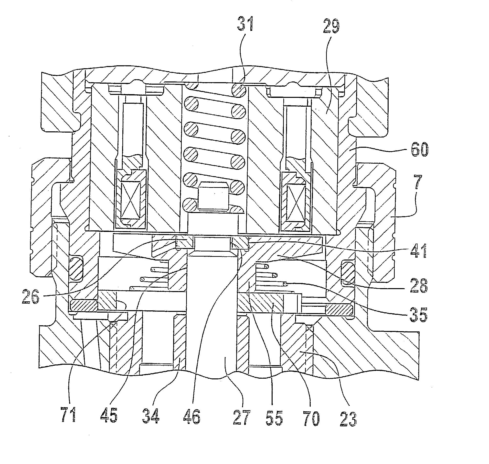
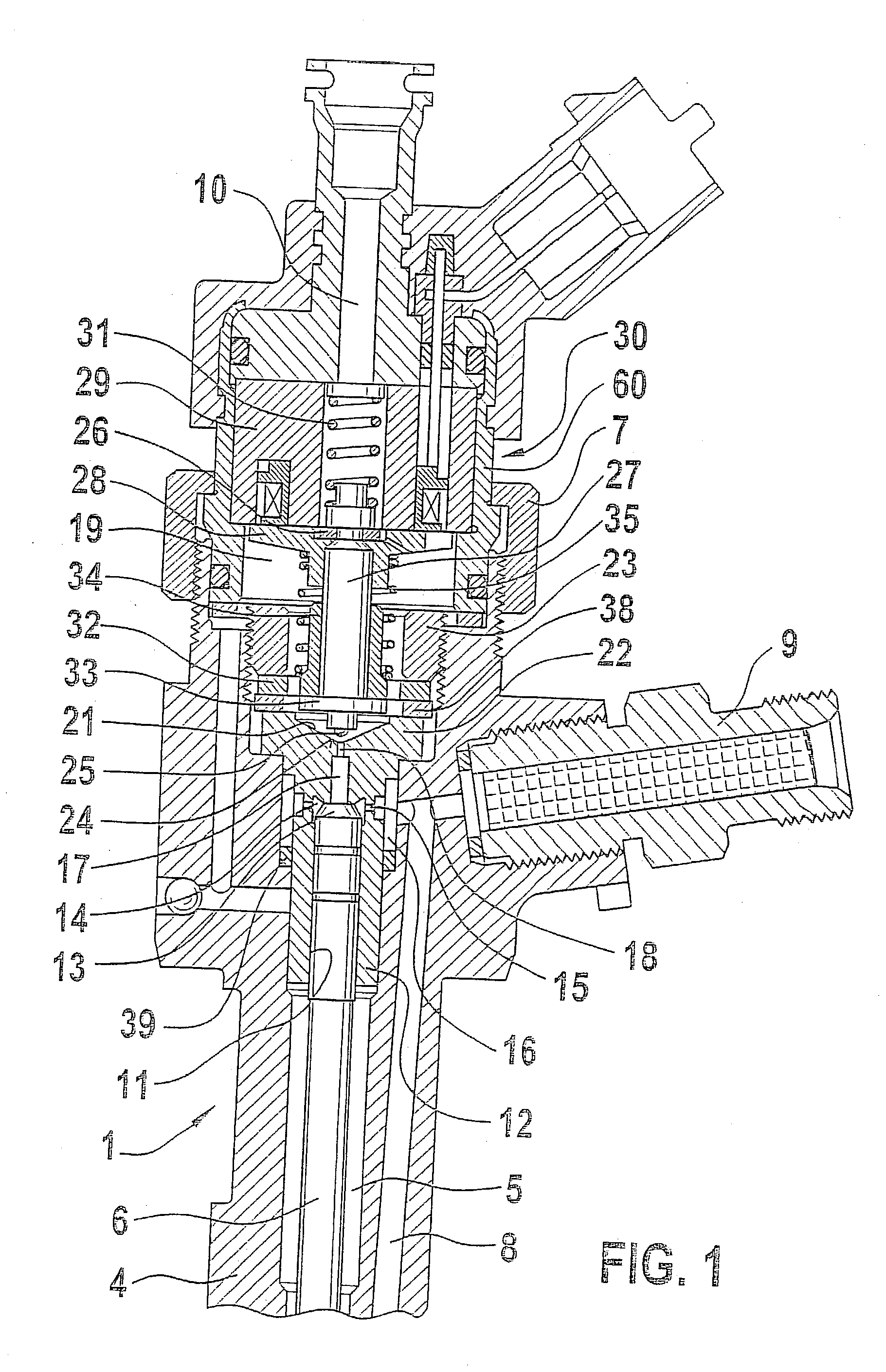
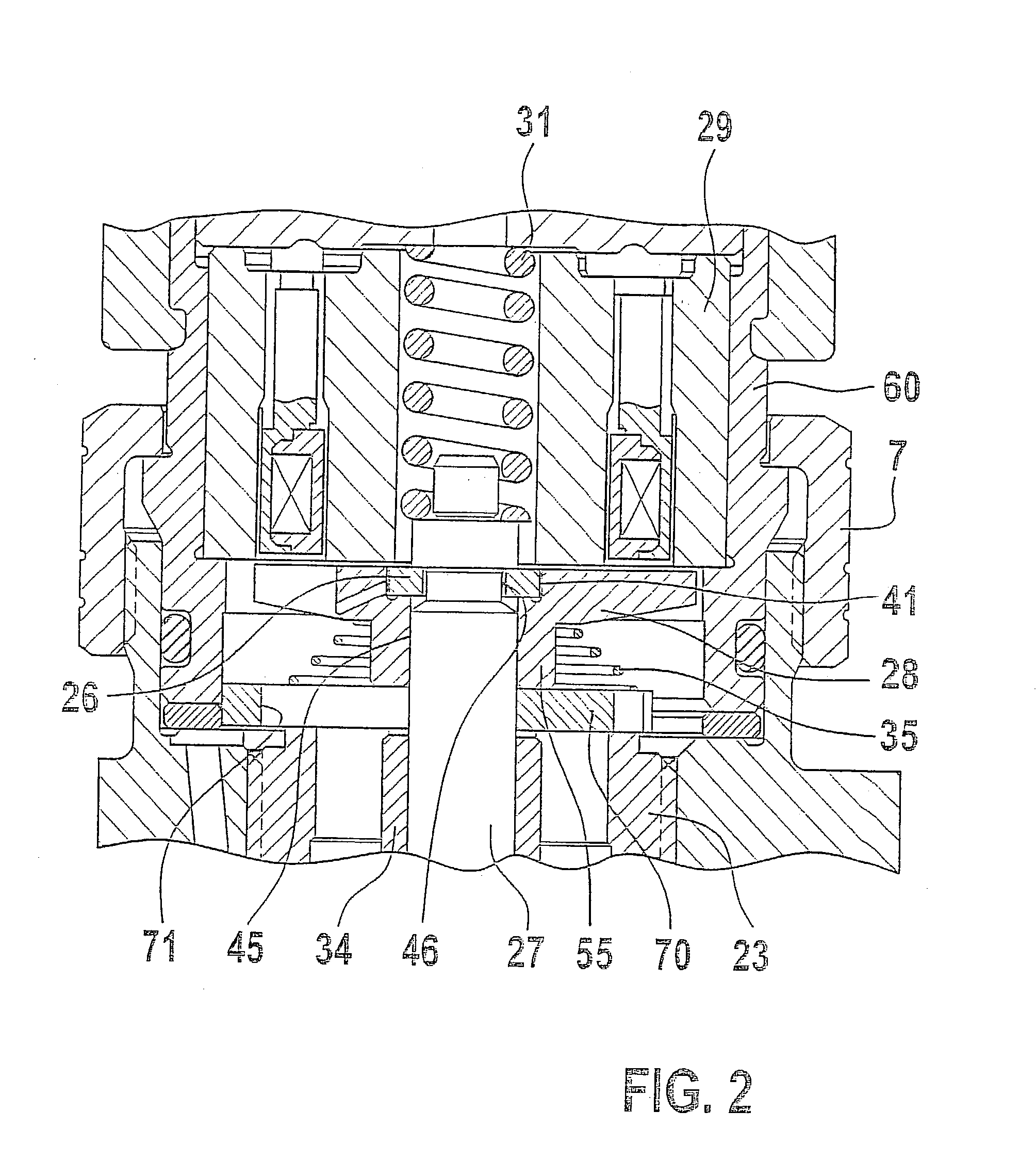
[0018] FIG. 1 shows the upper portion of a fuel injector 1 known from the related art which is intended for use in a fuel injection system equipped with a high-pressure fuel accumulator which is continuously supplied with high-pressure fuel via a high-pressure feed pump. The illustrated fuel injector 1 has a valve housing 4 which contains a longitudinal borehole 5 in which a valve piston 6 is situated whose one end acts on a valve needle mounted in a nozzle body (not shown). The valve needle is situated in a pressure chamber which is supplied with high-pressure fuel via a pressure borehole 8. During an opening stroke displacement of valve piston 6, the valve needle is lifted against the closing force of a spring by the high fuel pressure in the pressure chamber which constantly acts on a pressure shoulder of the valve needle. The fuel is injected through an injection orifice, which is then connected to the pressure chamber, into the combustion chamber of the internal combustion engi...


PUM


Abstract

A solenoid valve for controlling a fuel injector of an internal combustion engine, including an electromagnet 29, a displaceable armature having an armature plate 28 and an armature pin 27, and a control valve element 25 which is displaced with the armature and which cooperates with a valve seat 24 for opening and closing a fuel discharge channel 17 of a control pressure chamber 14 of the fuel injector 1. The armature plate 28 is mounted on the armature pin 27 so as to be slidably displaceable in opposition to the tensioning force of a restoring spring 35 acting on the armature plate 28 under the influence of the inert mass of the armature plate in the closing direction of the control valve element 25, and is pressed by the restoring spring 35 in its rest state against a stop part 26 attached to the armature pin 27. The stop part 26 is designed to encircle the periphery of the armature pin 27 by more than 180° in a plane perpendicular to the direction of movement of the armature pin.

Description

BACKGROUND INFORMATION[0001] The present invention relates to a solenoid valve for controlling a fuel injector of an internal combustion engine according to the preamble of claim 1.[0002] Such a solenoid valve, known for example from German Patent Application 197 08 104 A1, is used for controlling the fuel pressure in the control pressure chamber of a fuel injector, such as the injector of a common rail injection system. The fuel pressure in the control pressure chamber controls the movement of a valve piston using which a fuel injector orifice in the fuel injector is opened or closed. The known solenoid valve has an electromagnet situated in a housing part, a displaceable armature, and a control valve element, acted upon by a closing spring in the closing direction and moved together with the armature, which cooperates with a valve seat of the solenoid valve and thereby controls the fuel discharge from the control pressure chamber. A known disadvantage of this solenoid valve is the...

Claims


Application Information

Patent Timeline
Patent Type & Authority Applications(United States)
IPC IPC(8): F02M51/06F02M47/02F02M59/46F02M61/16F02M63/00
CPCF02M47/027F02M61/168F02M63/0021F02M2547/003F02M2200/304F02M2200/306F02M63/0075F02M63/0022F02M63/022
Inventor RUTHARDT, SIEGFRIEDRAPP, HOLGERSCHOENFELD, DIRK
Owner ROBERT BOSCH GMBH
Why Eureka
Try Eureka