Cervical applicator for high dose radiation brachytherapy

a cervical applicator and high-dose radiation technology, applied in radiation therapy, other medical devices, therapy, etc., can solve the problems of hybrid treatment, inconvenient patient care, and inconvenient patient care, so as to minimize patient discomfort, improve intra-cervical brachytherapy delivery, and maintain therapeutic

Inactive Publication Date: 2003-08-14
PAXTON EQUITIES
View PDF0 Cites 51 Cited by
  • Summary
  • Abstract
  • Description
  • Claims
  • Application Information

AI Technical Summary

Benefits of technology

[0015] It is another object of this invention to provide a highly efficient and efficacious intracervical and intervaginal brachytherapy delivery system.
[0016] Another object of this invention is to provide selective attenuation of radiation emitted from an internally disposed radiation source without reducing dose rate exposure to a selected target.
[0018] It is still another object of the invention to improve intra-cervical brachytherapy delivery while minimizing patient discomfort and inconvenience.
[0019] Still another object of the invention is to maintain therapeutic efficacy and maximize delivery efficiencies of intra-cervical and transvaginal brachytherapy.
[0021] A final stated, but only one of additional numerous objects of the invention, is to provide a radiation attenuating apparatus and method that is at once effective, inexpensive and easily deployed in for HDR brachytherapy procedures.
[0036] In general terms, the invention herein contemplates a brachytherapy method and adjunct calling for the transvaginal insertion of a cervical applicator providing a projecting tube portion for intra-cervical disposition and a combination radiation attenuating, tube-position-stabilizing balloon for in situ inflation. Upon inflation, the selected position of the applicator is thereby fixed relative to the vaginal canal and uterine cavity by, at minimum, an interference fit with the vaginal wall and cervix, and more desirably, by pressing with sufficient force on the vaginal wall to induce displacement thereof from the tube and to provide selected radiation attenuating shielding of nearby healthy tissues. Once the health care provider is satisfied with the physical disposition of the device and shielding the radiation source may be introduced in the conventional manner through the tube passage and to the proximal tip of the tube which, ideally has been positioned at or near the target tissue / mass. As a consequence, the balloon protects internal tissues / organs adjoining the vagina by increasing the distance thereof the radioactive source as well as providing attenuating shielding to significantly decreasing radiation exposure during HDR of the organ / tissue.

Problems solved by technology

The conventional Fletcher-Suit system design suffers from a known in situ positioning problem attributed, in part, to the absence of a secure connection between the colpastat tubes and the tandem tube.
Notwithstanding significantly enhanced radiation delivery efficiencies, many hospitals and medical treatment providers have opted not to use HDR treatments due to reportedly higher incidences of complications of which the most frequent complications arise from radiation damage to healthy tissues and organs proximate to the implanted / embedded radiation source.
Thus, while reportedly reducing the risk of complications, such hybrid treatments also represent a corresponding loss of delivery efficiencies.
Furthermore, prolonged procedures result in patient aggravation, inconvenience, and discomfort while also significantly increasing treatment costs attributable to extended hospitalization, all without any significant augmentation in efficacy.
However, such shielding is difficult to use and difficult to position in situ.
Even minor displacement of selective radiation attenuating shielding in situ defeats the benefit provided thereby.
If displaced, the shielding not only fails to diminish exposure of healthy tissues but also may obstruct exposure of targeted proliferative tissues.
Moreover, the use of effective shielding is increasingly difficult where the applicator embodies complicated structures that either interfere with or are interfered with by the shielding.
However, the very radiation attenuating excellence also obstructs efficient monitoring of the general area by electromagnetic-based instrumentation, for example, tomographs, magnetic resonance imagers, etc. and the more traditional x-rays and fluoroscopes.
Finally, conventional shielding does not contribute to stable positioning of the applicator during treatment in conjunction with its function to shield healthy tissue from exposure.

Method used


Image

  • Cervical applicator for high dose radiation brachytherapy
  • Cervical applicator for high dose radiation brachytherapy

Examples


Embodiment Construction

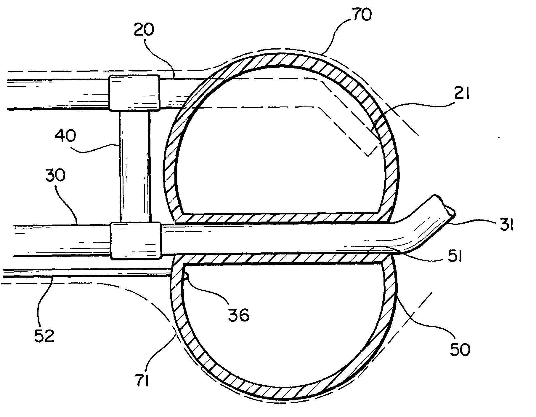
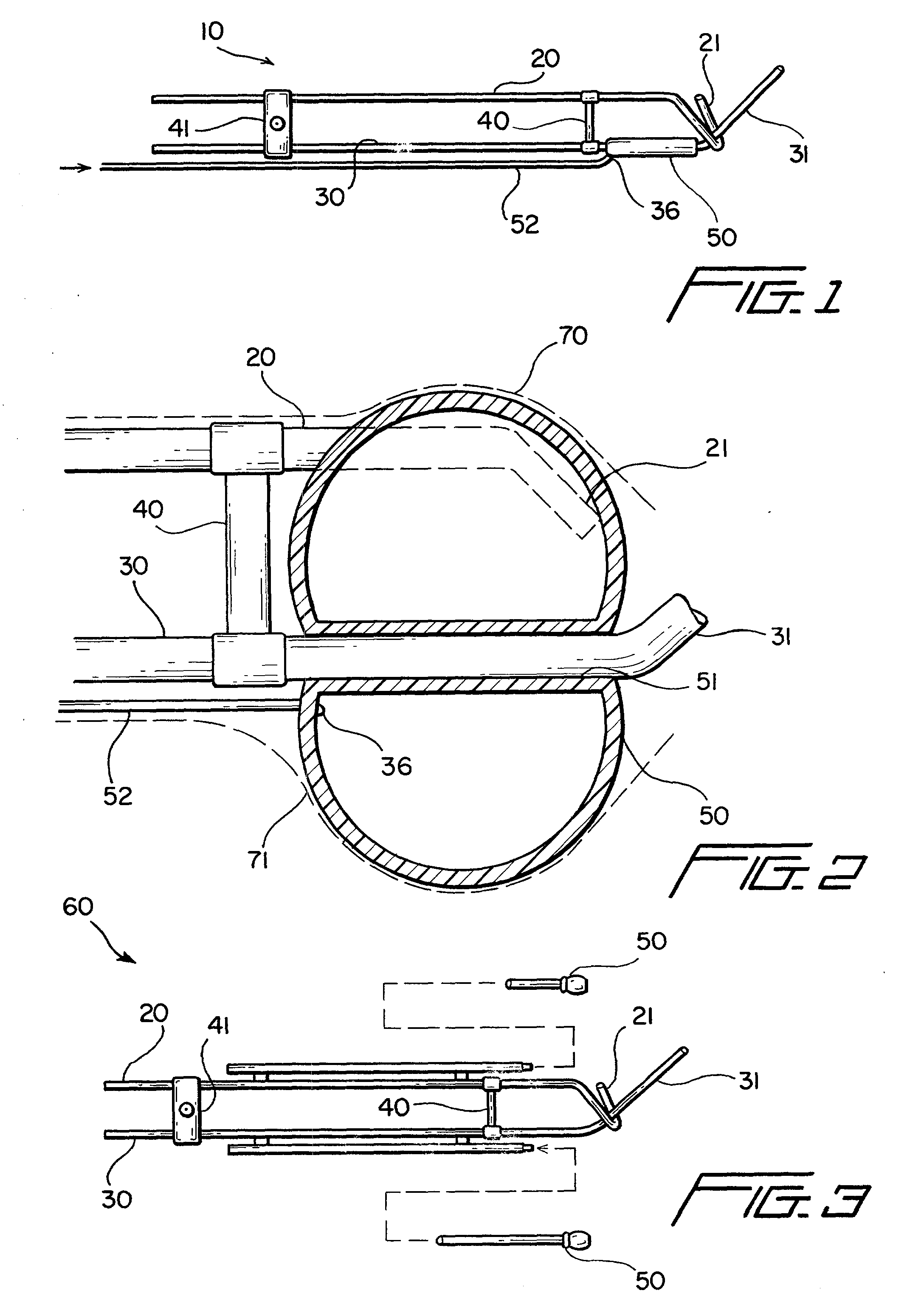
[0046] Two embodiments of a Fletcher-Suit type cervical applicator according to the present invention are now described making reference to the accompanying drawings. FIGS. 1 and 2 illustrate a first embodiment of a cervical applicator 10 and FIG. 3 represents an alternative embodiment, applicator 60. The applicator 10 of FIG. 1 comprises, as its major components intravaginal tube 20, a distal, angled cervix ring 21, a hollow, transvaginal-intracervical tube 30 including a intracervical projection portion 31, a bridge 40, a bridge 41, an inflatable balloon 50, and a fluid channel tube 52.

[0047] In more detail, the colpastat-intravaginal tube 20 is formed from an appropriate rigid, medical grade material such as surgical stainless steel, titanium, carbonate polymers, or other suitable materials providing adequate strength, rigidity, and sterilizable surfaces. The tube 20, preferably having a circular cross-section, may be solid or hollow. In the hollow form, the tube 20 effectively, ...


PUM


Abstract

A modified Fletcher-Suit tandem tube applicator includes a balloon which can be inflated to both positionally secure the applicator within the vaginal canal and to distend the confronting vaginal wall thereby increasing the distance of such tissue from the radioactive source contained in the tandem tube of applicator and correspondingly reducing radiation damage to nearby tissues and organs such as the rectum and bladder.

Description

[0001] This application claims priority to U.S. application Ser. No. 09 / 588,697, filed Jun. 7, 2000, said patent application being hereby incorporated by reference.I. BACKGROUND OF THE INVENTION[0002] A. Field of the Invention[0003] This invention relates to a modified Fletcher-Suit after-loading cervical applicator for use in brachytherapy. The invention includes a tandem and colpastat tube arrangement permitting introduction of radio-emissive material to intracervical tissues where the tubes are combined with at least one balloon that is inflatable in situ with a radiation attenuating fluid to positionally stabilize the applicator in the patient and provide selective shielding during high dose rate brachytherapy.[0004] B. Description of the Art[0005] Since shortly after the Curies' discovered radioactivity, radiotherapy has been used in connection with treatment of proliferative tissues and, particularly, in connection with cancer treatments and other oncological procedures. The t...

Claims


Application Information

Patent Timeline
Patent Type & Authority Applications(United States)
IPC IPC(8): A61N5/10
CPCA61N5/1016
Inventor HARMON, MICHAEL
Owner PAXTON EQUITIES
Why Eureka
Try Eureka