Fuel vaporization promoting apparatus and fuel carburetion accelerator

a fuel carburetion accelerator and vaporization promotion technology, which is applied in the direction of combustion-air/fuel-air treatment, combustible gas purification/modification, and separation processes, etc., can solve the problems of increasing power consumption, increasing the amount of fuel consumed, and not always improving the method of fuel spray vaporization

Inactive Publication Date: 2003-08-21
HITACHI LTD +1
View PDF12 Cites 8 Cited by
  • Summary
  • Abstract
  • Description
  • Claims
  • Application Information

AI Technical Summary

Problems solved by technology

However, this method is not always sufficient for improvement of fuel spray vaporization.
For a conventional system of such structure, the flow of air along the inner wall surface of the heater becomes nonuniform and when the fuel comes into contact with the inner wa

Method used


Image

  • Fuel vaporization promoting apparatus and fuel carburetion accelerator
  • Fuel vaporization promoting apparatus and fuel carburetion accelerator
  • Fuel vaporization promoting apparatus and fuel carburetion accelerator

Examples


Embodiment Construction

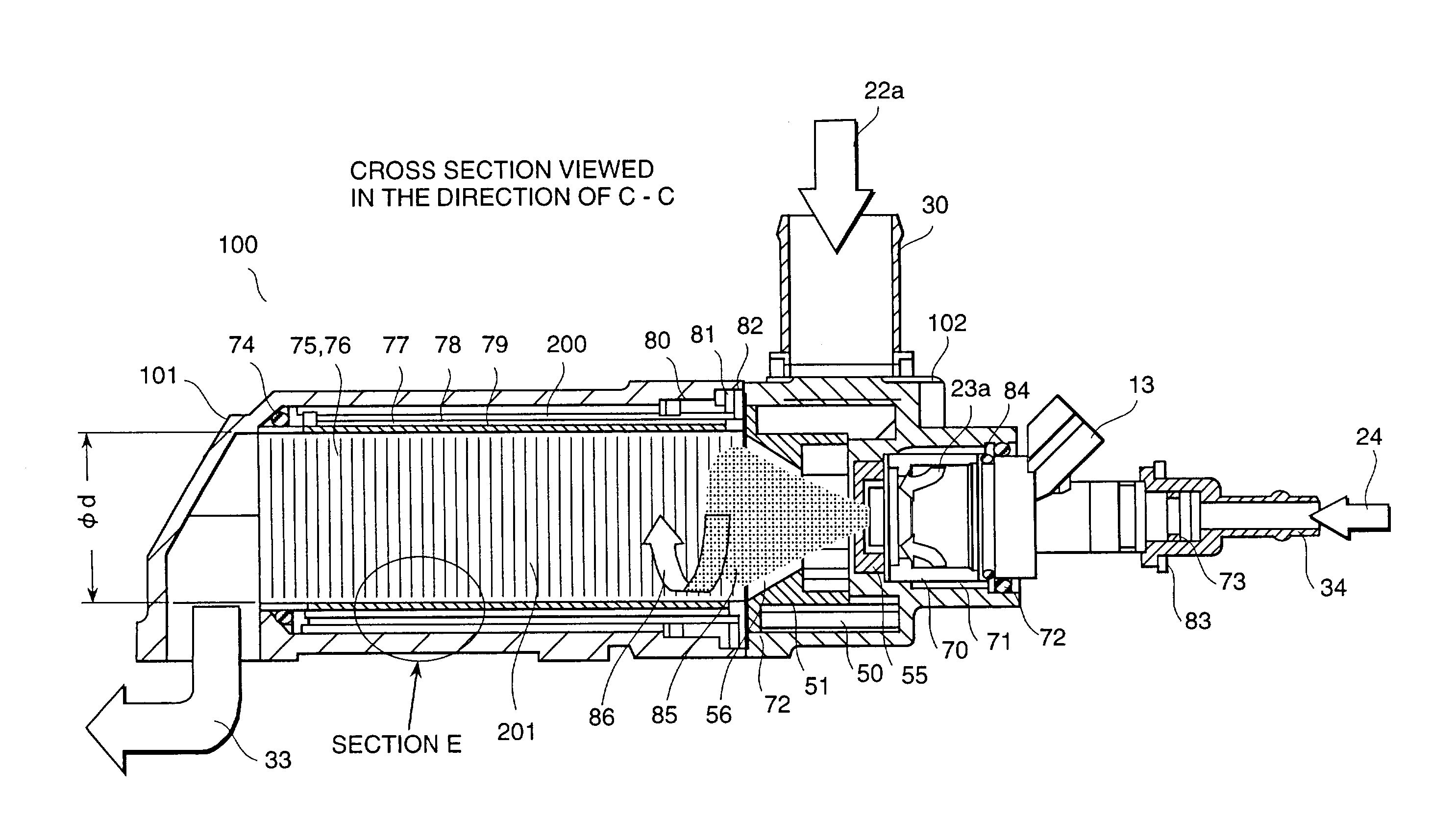
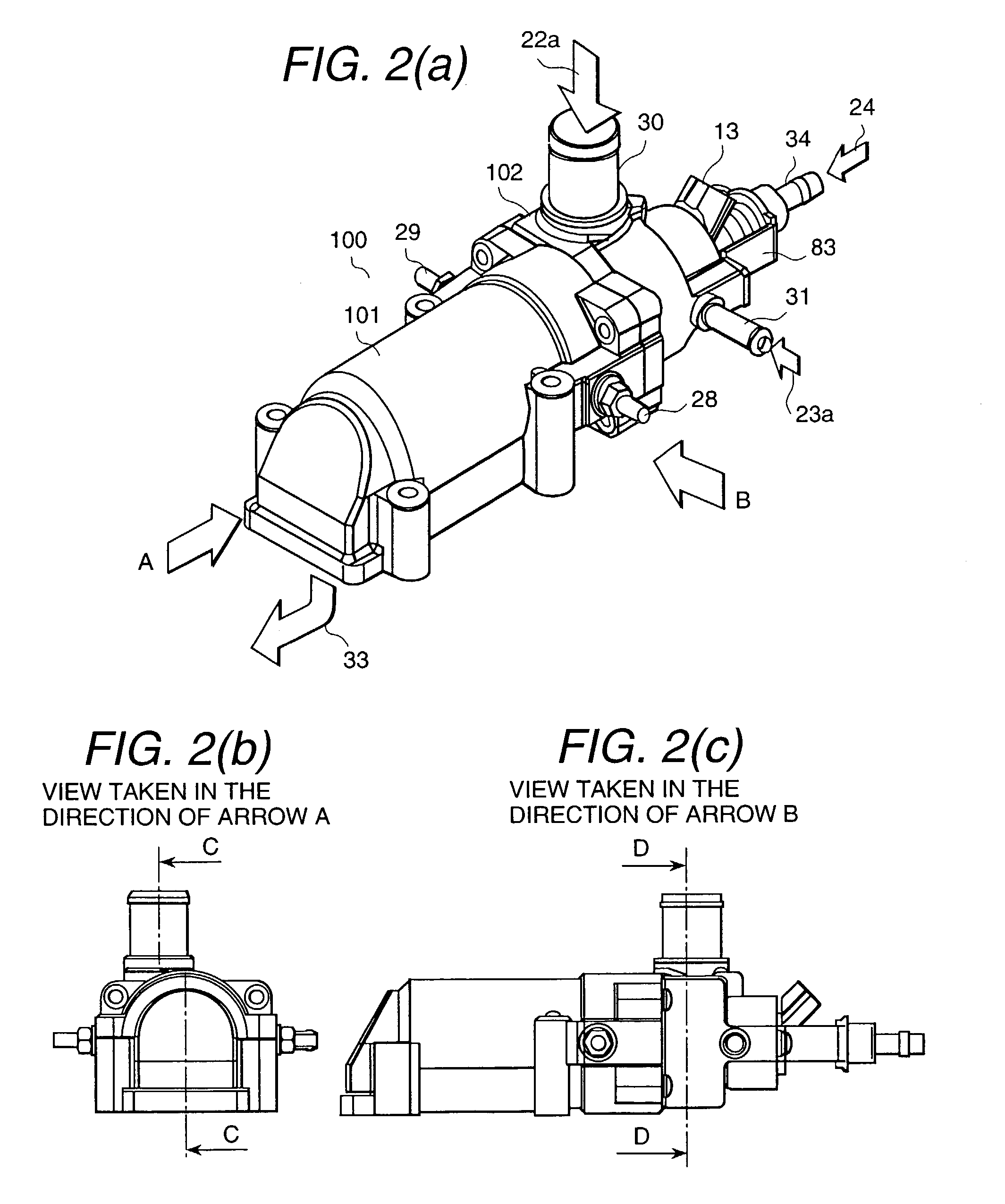
[0089] The following describes an embodiment of the present invention with reference to FIGS. 1 to 8.

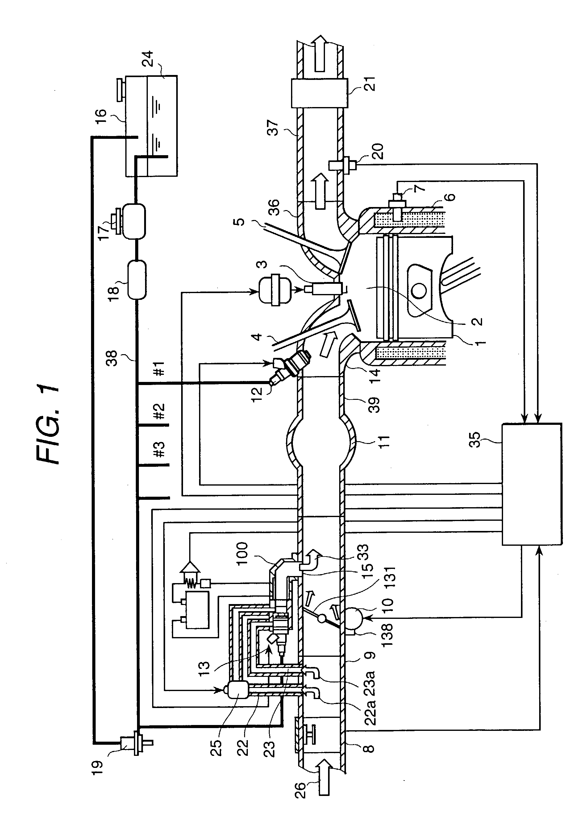
[0090] FIG. 1 is a diagram representing an internal combustion engine 1 which is a known ignition type internal combustion engine using gasoline as fuel. This figure gives attention to only one cylinder.

[0091] The above stated internal combustion engine. 1 has an ignition plug 3 arranged in a combustion chamber 2, and comprises an intake valve 4 for sucking air and mixed air, and an exhaust valve 5 for discharging exhaust gas after combustion. The internal combustion engine 1 comprises a water temperature sensor 7 for detecting the temperature of an engine coolant 6, and a rotary sensor (not illustrated) for detecting engine speed on the side of the combustion chamber 2, and these sensors are used to detect operating conditions.

[0092] The intake system for sucking gas into the combustion chamber 2 comprises; an air flow sensor 8 for measuring the air 26 sucked after passing through a...


PUM

PropertyMeasurementUnit
Angleaaaaaaaaaa
Forceaaaaaaaaaa
Dispersion potentialaaaaaaaaaa

Abstract

The present invention promotes atomization and vaporization of spray at the time of cold startup and reduces the amount of fuel depositing on the inner wall of the intake manifold, thereby ensuring improved startability of an internal combustion engine of a car, reduced fuel costs and improved purification of exhaust gas. A very fine groove 201 is formed on a heat transfer surface 76 in a fuel vaporization promoting apparatus 100, wherein this groove 201 is shaped in such a way that fuel 24 is dispersed by the surface tension of a heat transfer surface 76 and fuel 24. This configuration ensures uniform dispersion of fuel 24 on the heat transfer surface 76 and effective promotion of vaporization

Description

[0001] 1. Field of the Invention[0002] The present invention relates to a fuel supply technique for ensuring excellent combustion of fuel in the internal combustion engine of an automobile.[0003] The present invention relates to a fuel carburetion accelerator for accelerating the carburetion of the fuel supplied to an automobile-use internal combustion engine, and the fuel carburetion accelerator can be applied to both the type of combustion engine in which a fuel is injected to the air suction ports of each cylinder, and the type of combustion engine in which a fuel is injected directly to each cylinder.[0004] 2. Prior Art[0005] To improve startability of an internal combustion engine, reduce fuel costs, to purify exhaust gas and decrease reduce HC gas in purification of exhaust gas, it is effective to reduce the deposition of fuel on the inner wall surface of an intake manifold by atomizing and vaporizing fuel spray injected by an fuel injection valve (injector). Further, fuel sta...

Claims


Application Information

Patent Timeline
IPC IPC(8): F02M15/04F02M31/125F02M31/135F02M33/06
CPCF02M15/04F02M31/125F02M31/135Y10S261/55Y02T10/126Y10S261/25Y10S261/83F02M33/06Y02T10/12
Inventor AMOU, KIYOSHIKADOMUKAI, YUZOSAEKI, HIROAKIWATANABE, KENJIICHIHARA, TAKANOBUNAGANO, MASAMI
Owner HITACHI LTD
Why Eureka
Try Eureka