Apparatus and method of recovering reactive power of plasma display panel

a technology of display panel and reactive power, which is applied in the direction of instruments, static indicating devices, etc., can solve the problems of large complicated circuit construction for recovering energy itself, and high power consumption of each switching device and diode, so as to reduce the overshoot voltage

Inactive Publication Date: 2003-08-21
SAMSUNG ELECTRONICS CO LTD
View PDF2 Cites 8 Cited by
  • Summary
  • Abstract
  • Description
  • Claims
  • Application Information

AI Technical Summary

Benefits of technology

[0016] According to another aspect of the invention, the plasma display panel further comprises a resistor connected in series to the power connecting switch in order to reduce an overshoot voltage.
[0021] According to a yet further aspect of the invention, a resistor is connected in series to the power connecting switch, thereby reducing overshoot voltage.

Problems solved by technology

However, in the conventional reactive power recovering circuit, the construction of the circuit for recovering the energy itself has been very complicated.
In addition, the amount of power consumed by each switching device and each diode, to which a plurality of switching devices and a diode to prevent a reverse flow are connected in series, has been large.

Method used


Image

  • Apparatus and method of recovering reactive power of plasma display panel
  • Apparatus and method of recovering reactive power of plasma display panel
  • Apparatus and method of recovering reactive power of plasma display panel

Examples


Embodiment Construction

[0029] Hereinbelow, the present invention will be described in more detail with reference to the accompanying drawings, wherein like reference numerals refer to the like elements throughout. The embodiments are described below in order to explain the present invention by referring to the figures.

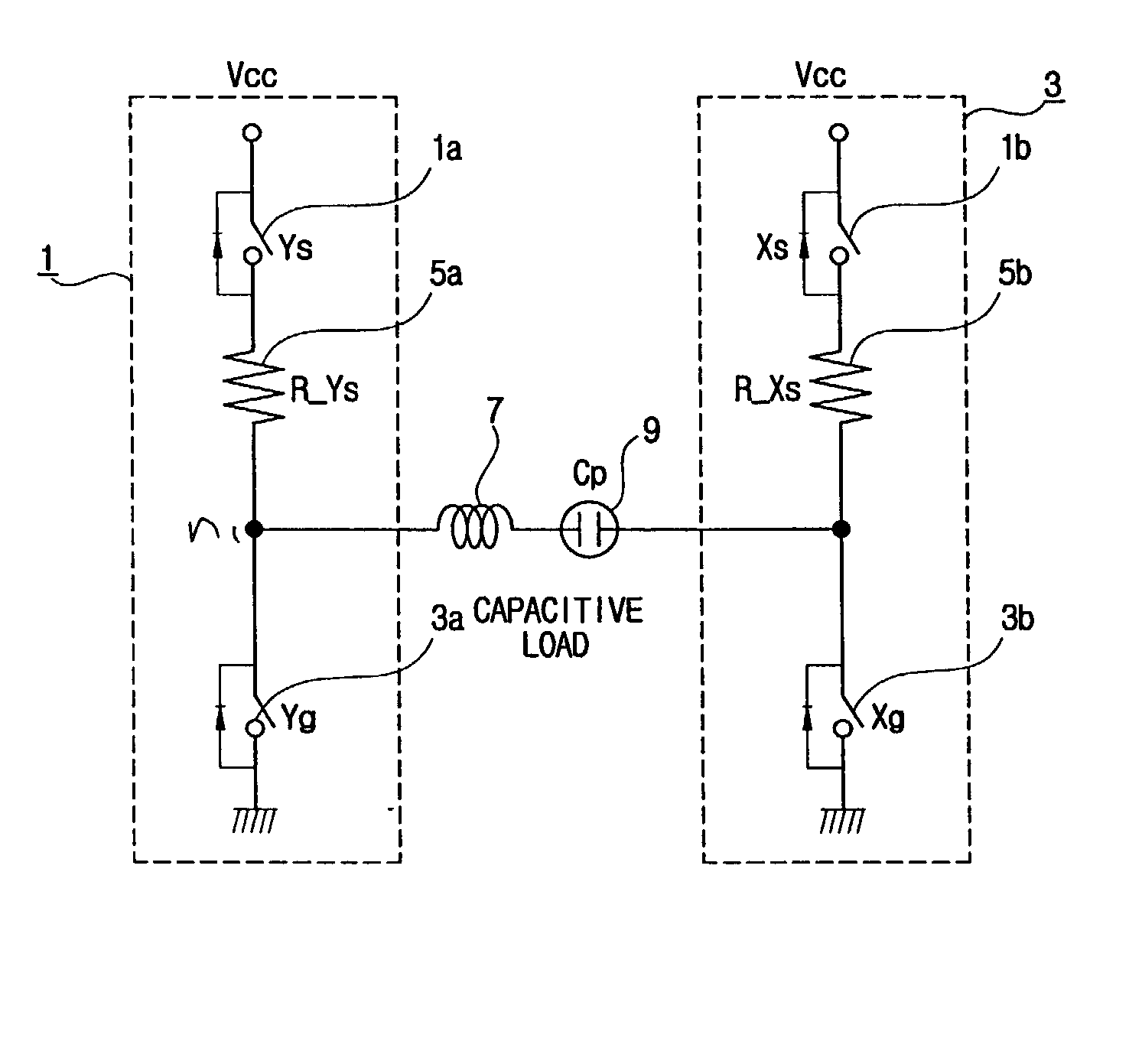
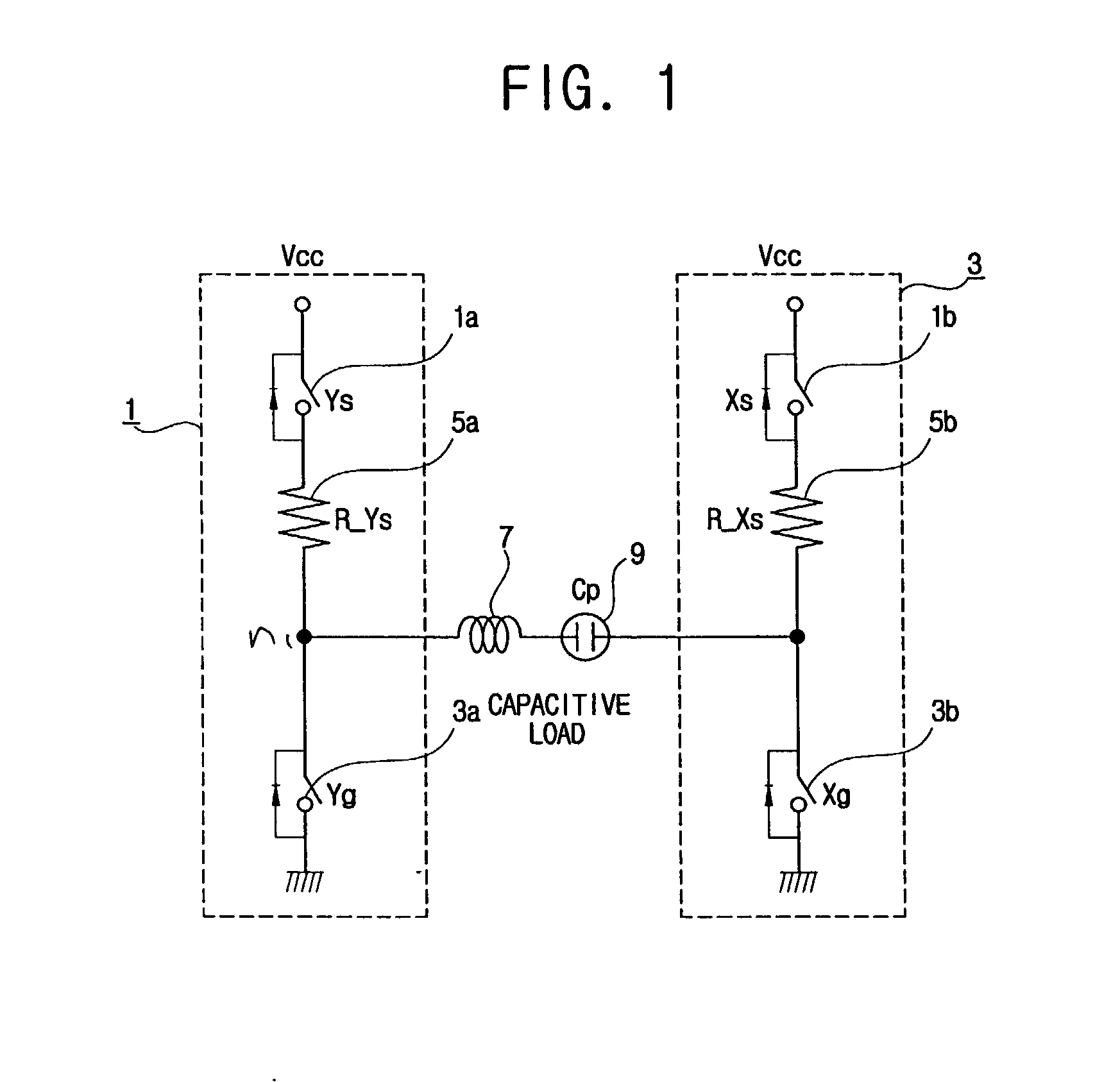
[0030] FIG. 1 is a block diagram of a reactive power recovering circuit of a PDP according to an embodiment of the present invention. As illustrated therein, a driving circuit driven to generate an electric discharge in discharge sustaining electrode pairs includes a Y-electrode unit driving cell 1 to drive the Y-electrode of the discharge sustaining electrode pair. X-electrode unit driving cells 3 drive the X-electrodes. A controller (not shown) applies a control signal to drive the Y-electrode unit driving cell 1 and the X-electrode unit driving cells 3. A panel capacitor 9 indicates an equivalent capacitance formed between the Y-electrode and the X-electrode in the panel.

[0031] The Y-elec...


PUM


Abstract

An apparatus to recover a reactive power of a plasma display panel, the apparatus including a power supply source, first and second discharge electrodes to perform a surface discharge with a voltage from the power supply source, a panel capacitor having opposite ends connected to the respective discharge electrodes and which is discharged by supplying a charge voltage to one of the first and second discharge electrodes, an inductor provided between the one of the first and second discharge electrodes and the panel capacitor. The inductor is charged by a discharge current of the panel capacitor and induces the charge voltage of the panel capacitor to be recovered.

Description

[0001] This application claims the benefit of Korean Application No. 2002-8786, filed Feb. 19, 2002, in the Korean Intellectual Property Office, the disclosure of which is incorporated herein by reference.[0002] 1. Field of the Invention[0003] The present invention relates in general to a plasma display apparatus which displays images thereon by use of an electric discharge, and more particularly, to a plasma display panel (hereinafter, a "PDP") having a circuit to recover reactive power.[0004] 2. Description of the Related Art[0005] A PDP is an apparatus that allows pictures to be displayed thereon using a gas discharge. Depending upon types of methods used to drive the PDP, the PDP is largely categorized into a direct current (DC) type PDP, which performs a facing discharge, and an alternating current (AC) type PDP, which performs a surface discharge. The AC type PDP is more advantageous since it has a lower power consumption and a longer lifetime in comparison with the DC type. F...

Claims


Application Information

Patent Timeline
Patent Type & Authority Applications(United States)
IPC IPC(8): G09G3/28
CPCG09G2310/066G09G3/2965G09G3/296
Inventor KANG, CHUN-SEONG
Owner SAMSUNG ELECTRONICS CO LTD
Why Eureka
Try Eureka