Clock recovery circuitry

a clock recovery and circuit technology, applied in the field of clock recovery circuitry, can solve the problems of increasing the jitter of the recovered clock signal, requiring many clock cycles for the phased locking loop to lock onto the data, and a relatively large proportion of the total transmission time being used for clock recovery

Inactive Publication Date: 2003-08-28
SOCIONEXT INC
View PDF8 Cites 59 Cited by
  • Summary
  • Abstract
  • Description
  • Claims
  • Application Information

AI Technical Summary

Problems solved by technology

A problem in known clock recovery circuits is that it may take many clock cycles for the phased locked loop to lock onto the data signal, in particular if high speed data signals are being received.
If data is received in bursts, then the phase locked loop may need to lock onto each burst of data separately, which may result i

Method used


Image

  • Clock recovery circuitry
  • Clock recovery circuitry
  • Clock recovery circuitry

Examples


Embodiment Construction

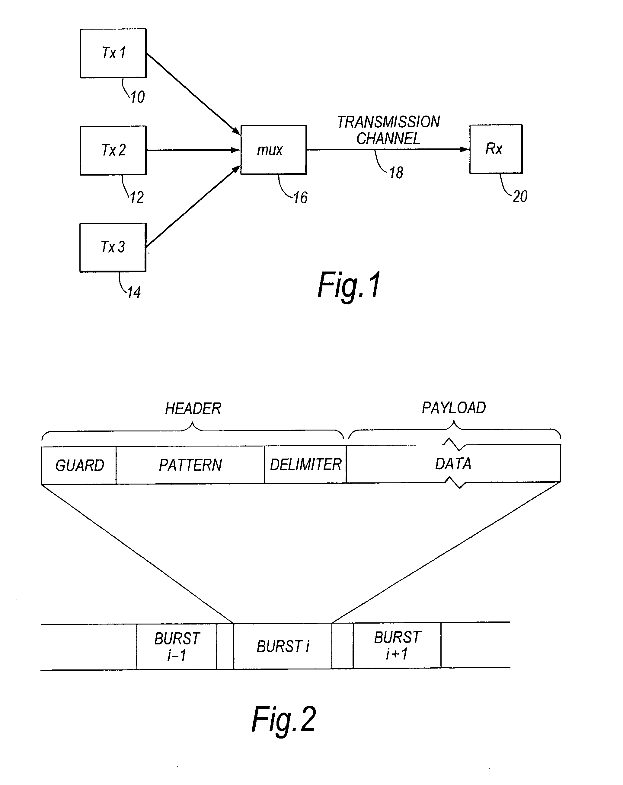
[0046] FIG. 1 shows parts of an example communications system with which the present invention may be used. In FIG. 1, three transmitters 10, 12, 14 each transmits a serial data signal. The transmitters operate on a time division multiplex basis, with each transmitter being allocated a window in which it may transmit a burst of data. The various data signals are combined in multiplexer 16, transmitted over transmission channel 18, and received by receiver 20.

[0047] The transmitters 10, 12, 14 are arranged such that each transmitter transmits a data signal at the same frequency as the other transmitters. However, due to differences in path length between the transmitters and the receiver, each data signal is received by the receiver with a difference phase. In the receiver, a clock and data recovery (CDR) circuit is provided, which recovers a clock signal from each data burst, and uses the clock signal to recover the data.

[0048] FIG. 2 shows an example of the format of the data burst...


PUM


Abstract

Clock recovery circuitry for recovering a clock signal from a data signal is disclosed. The clock recovery circuitry comprises sampling means (46) for sampling the data signal at a plurality of sampling points, bit reversal detecting means (48) for determining a sampling point at which the data signal changes state, selecting means (50) for selecting a phase from amongst a plurality of candidate phases based on a sampling point at which the data signal is determined to change state, and phase setting means (38) for setting the phase of the clock signal in dependence on the selected phase. The circuitry may be used to produce an estimate of a desired phase of the clock signal for supply to a phase locked loop. This can allow the phase locked loop to be brought quickly into lock.

Description

BACKGROUND TO THE INVENTION[0001] The invention relates to clock recovery circuitry for recovering a clock signal from a data signal.[0002] When receiving an asynchronous data signal, a clock signal is usually recovered from the received data signal and used to sample the data signal. Known clock recovery circuits use a phase locked loop to lock the phase of a reference clock to the phase of the received data signal, in order to recover a clock signal.[0003] A problem in known clock recovery circuits is that it may take many clock cycles for the phased locked loop to lock onto the data signal, in particular if high speed data signals are being received. If data is received in bursts, then the phase locked loop may need to lock onto each burst of data separately, which may result in a relatively large proportion of the total transmission time being used for clock recovery.[0004] In order to increase the speed with which a phase locked loop locks onto a data signal, it is possible to ...

Claims


Application Information

Patent Timeline
IPC IPC(8): H03L7/08H03L7/10H03L7/06H04L7/00H04L7/02H04L7/033
CPCH04L7/0004H04L7/0337H04L7/0331H04L7/033H04L7/04
Inventor SOU, ANTONY
Owner SOCIONEXT INC
Why Eureka
Try Eureka