Fuel-injection valve for internal combustion engines

a technology for internal combustion engines and fuel injection valves, which is applied in the direction of fuel injection apparatus, machine/engines, feed systems, etc., can solve the problems of increasing the fuel pressure, increasing the closing force of the valve member, and metering and controlling the injection

Inactive Publication Date: 2003-09-04
ROBERT BOSCH GMBH
View PDF6 Cites 1 Cited by
  • Summary
  • Abstract
  • Description
  • Claims
  • Application Information

AI Technical Summary

Problems solved by technology

The spring chamber is closed off except for this throttle gap, so that fuel that flows through the throttle gap into the spring chamber causes an increase in the fuel pressure there and thus an increased closing force on the valve member.
However, the known fuel injection valve has the disadvantage that the fuel pressure in the spring chamber does not drop all the way between injections, and thus a high static pressure is

Method used


Image

  • Fuel-injection valve for internal combustion engines
  • Fuel-injection valve for internal combustion engines
  • Fuel-injection valve for internal combustion engines

Examples


Embodiment Construction

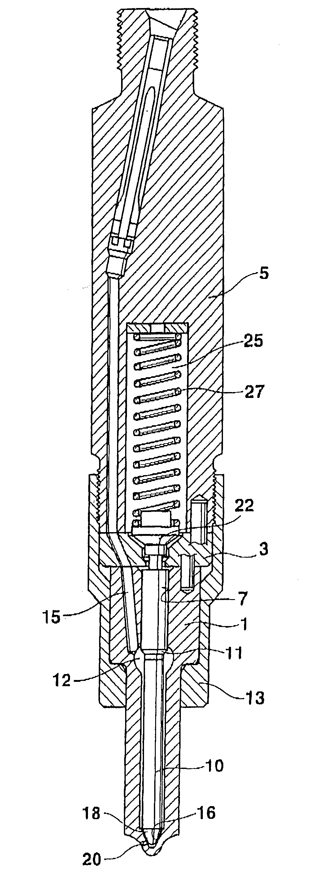
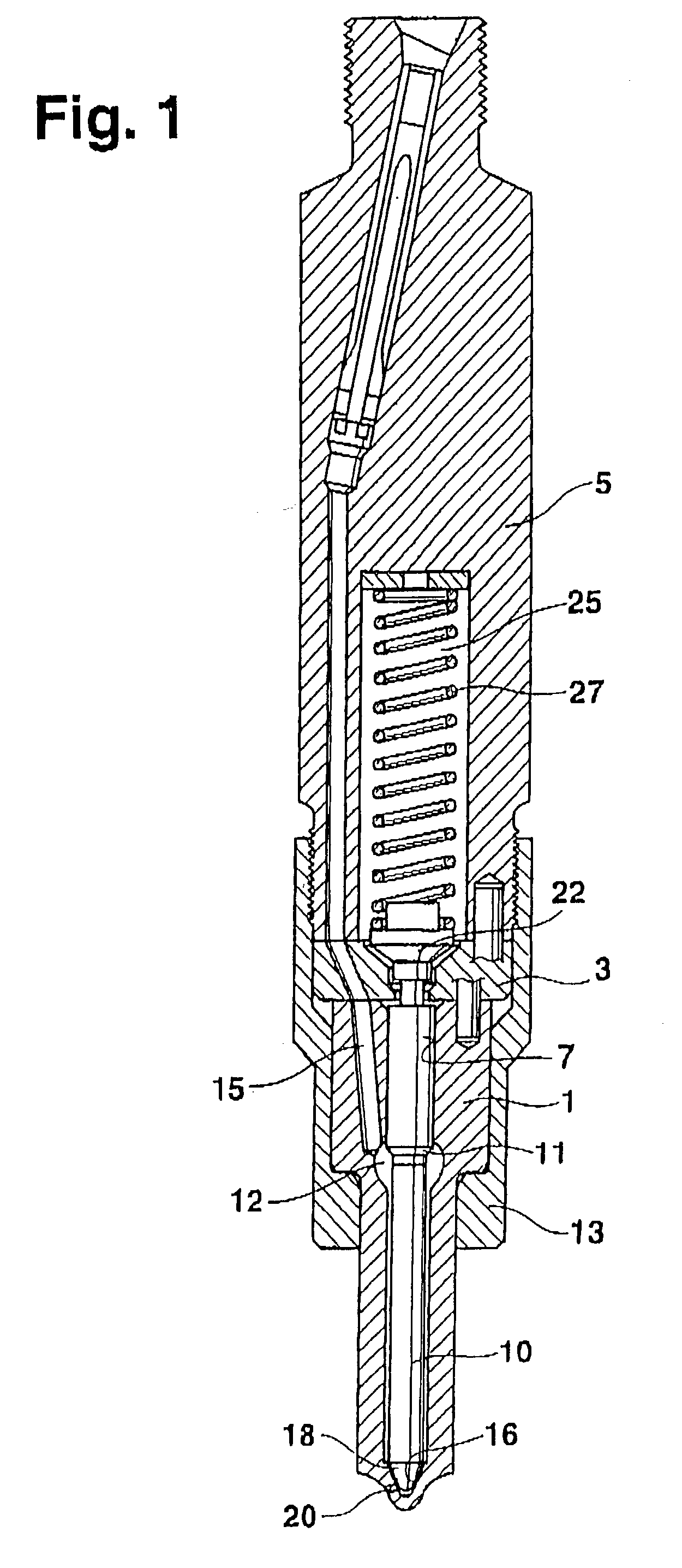
[0014] In FIG. 1, a longitudinal section through a fuel injection valve of the invention is shown. A valve body 1 is braced in the axial direction against a valve holding body 5 by means of a lock nut 13, with the interposition of a shim 3. A bore 7 is embodied in the valve body 1, and a valve seat 16 is embodied on the end of the bore toward the combustion chamber; at least one injection opening 20 is disposed in the valve seat and connects the bore 7 with the combustion chamber of the internal combustion engine. A valve member 10 is disposed in the bore 7; it is guided in the bore 7 in a portion remote from the combustion chamber, and it tapers toward the combustion chamber, forming a pressure shoulder 11. On the end of the valve member 10 toward the combustion chamber, there is a valve sealing face 18, which cooperates with the valve seat 16 for controlling the at least one injection opening 20. A pressure chamber 12 is embodied in the valve body 1; it is formed by a radial enlar...


PUM


Abstract

A fuel injection valve with a valve member (10), which cooperates with a valve seat (16) to control injection openings (20). The valve member (10) is guided, in a portion remote from the combustion chamber, in a bore (7) and is surrounded by a pressure chamber (12), which can be filled with fuel at high pressure. The valve member (10) is urged by a spring (27) disposed in a spring chamber (25) and having a closing force in the direction of the valve seat (16), and in an appropriate opening pressure in the pressure chamber (12), as a result of the hydraulic pressure on a pressure shoulder (11), embodied on the valve member (10), the valve member lifts from the valve seat (10) and thus opens the injection openings; the injection of the fuel is effected separately in a main injection and a subsequent postinjection. The pressure chamber (12) and the spring chamber (25) communicate via a throttle connection, so that the pressure in the otherwise closed-off spring chamber (25) rises during the main injection and via the additional hydraulic force on the valve member (10) raises the opening pressure of the postinjection; the pressure in the spring chamber (25) has reached the initial value again by the onset of the next injection cycle (FIG. 1).

Description

PRIOR ART[0001] The invention is based on a fuel injection valve as generically defined by the preamble to claim 1. One such fuel injection valve is known for instance from German Published, Unexamined Patent Application DE 197 52 496 A1. The fuel injection valve includes a valve body, which is axially braced against a valve holder body. In the valve body, there is a bore in which a pistonlike valve member is disposed longitudinally displaceably. The valve member is guided, in a portion remote from the combustion chamber, in the bore, and on its end toward the combustion chamber it has a valve sealing face, which cooperates with a valve seat, embodied in the valve body, for controlling at least one injection opening. On the end remote from the combustion chamber, the valve member is joined to a spring plate, which protrudes into a spring chamber embodied in the valve holder body, and between which and the end toward the combustion chamber of the spring chamber, a spring is disposed ...

Claims


Application Information

Patent Timeline
IPC IPC(8): F02M45/08F02M61/10F02M61/20
CPCF02M61/205
Inventor POTSCHIN, ROGERALBRECHT, WOLFGANG
Owner ROBERT BOSCH GMBH
Why Eureka
Try Eureka