
Plausibility checking of current transformers in substations

a current transformer and substation technology, applied in non-electric variable control, process and machine control, instruments, etc., can solve the problems of parametrisation of measurement values, primary errors in the current transformer itself, and measurement values detected by the current transformer and the parameters of filtering and scaling

Inactive Publication Date: 2003-10-02
HITACHI ENERGY SWITZERLAND AG
View PDF18 Cites 12 Cited by
  • Summary
  • Abstract
  • Description
  • Claims
  • Application Information

AI Technical Summary

Benefits of technology

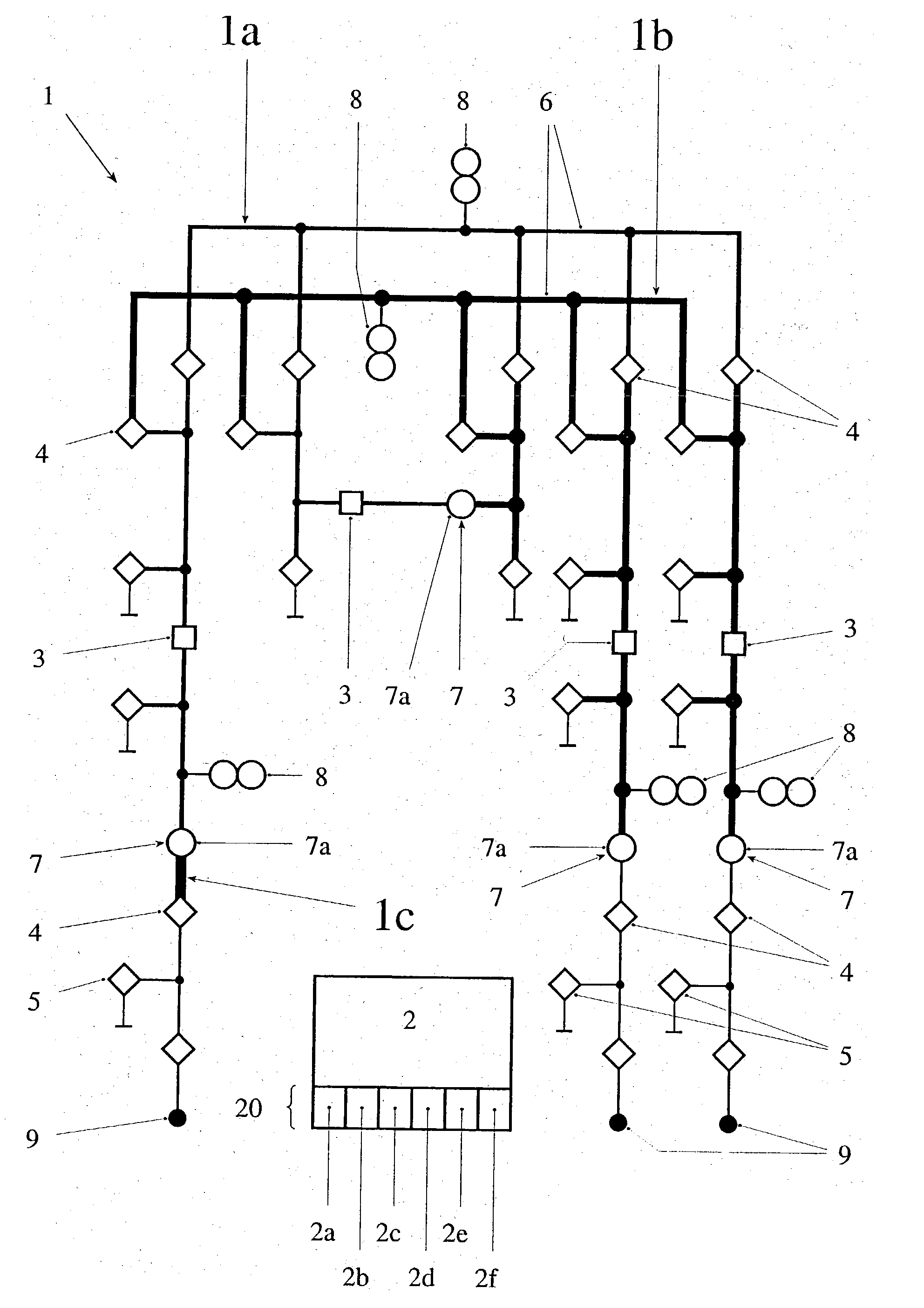
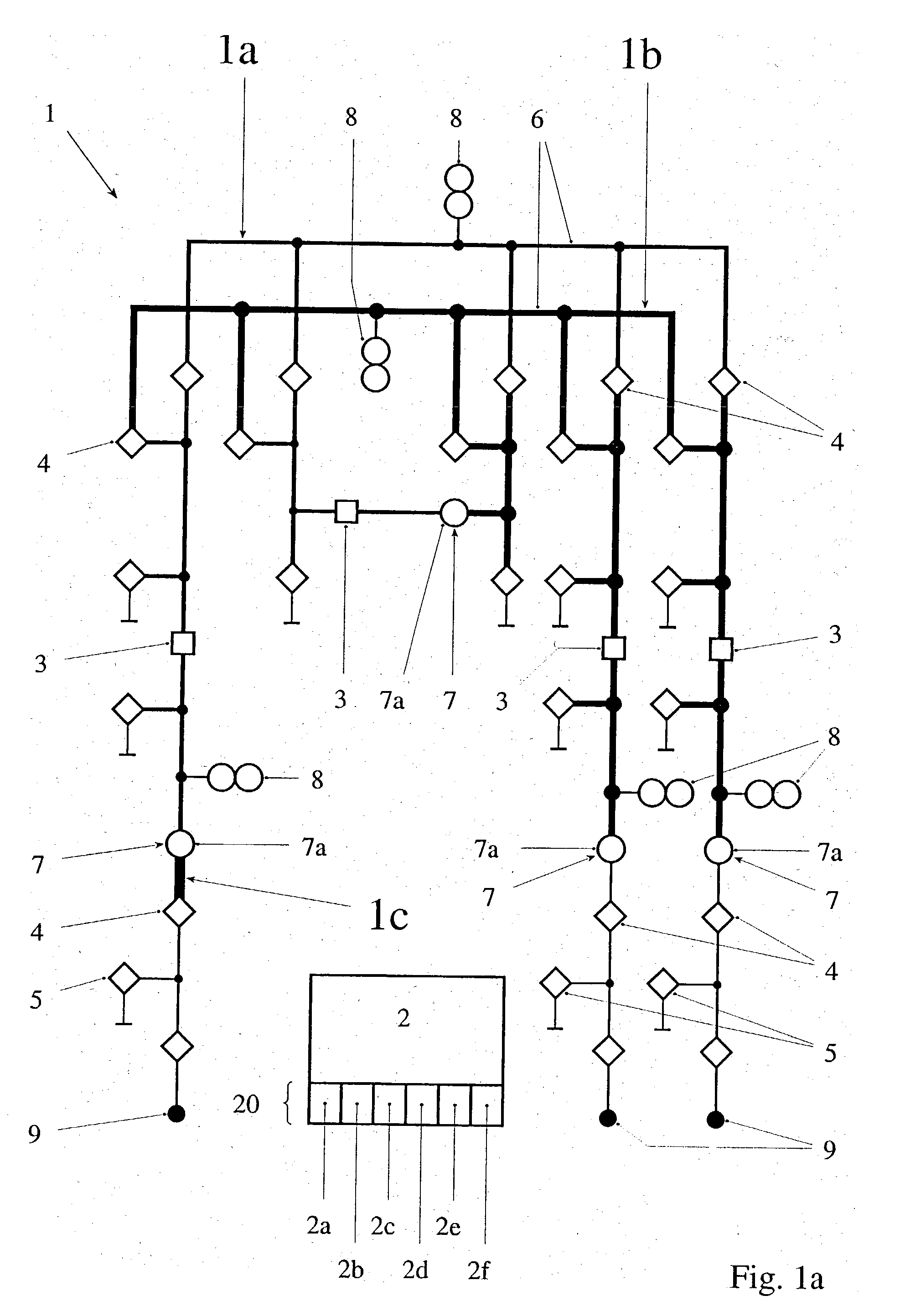
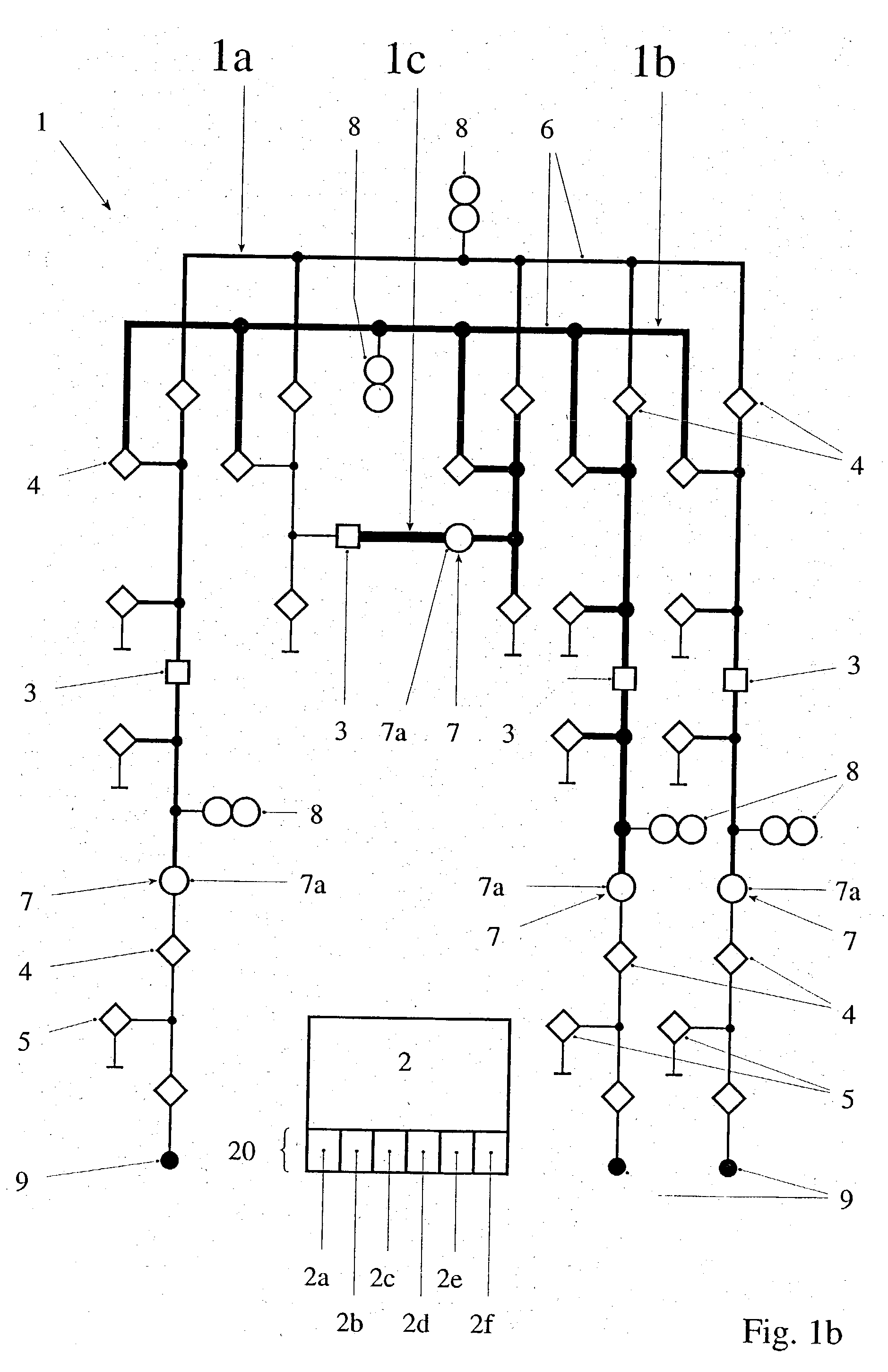
[0009] Thus, each zone represents a current node, the current sum of which is ideally zero. Open switches can be assigned a current measuring value of zero since they correspond to current transformers with a nominal current of zero. The test of the current sum for deviations from the ideal value of zero represents a simple, efficient method for checking, by means of a relative comparison of the current transformers of a zone, their scaling within permissible measurement signal deviations. The method requires little computing effort and no additional measuring expenditure in the current transformers. In particular, it is not necessary to know or estimate a correct or absolute current value. The identification of current transformers as problematic represents a first warning or alarm stage and signals that further monitoring of the current transformers of this zone is required. The method is independent of the configuration or the network arrangement of the primary devices of the switchgear and, in particular, independent of the complexity of their networking and, therefore, can be implemented for any desired arrangements without significant adaptations. The method is also independent from the instantaneous operating state of the switchgear and, in particular, can also be performed with fluctuating current values. Tracking the topology is done dynamically, i.e. the topology or the division into zones is updated continuously or on demand. In particular, it can change due to switching actions. It is also advantageous that measuring signals of the current transformers already available in the control system can be accessed. The method is also compatible with conventional local plausibility tests for current transformers. Going beyond these, however, it allows slight deviations or errors in the scaling of current transformers to be detected. More severe faults or defects on the primary side of current transformers can also be detected.
[0015] The exemplary embodiment as claimed in claim 7 has the advantage that it is possible to operate the switchgear with calculated currents.

Problems solved by technology

Both the measurement values detected by the current transformer and the parameters of the filtering and scaling, i.e. the so-called parametrisation of the measurement values can have errors.
Primary errors in the current transformer itself are produced e.g. by defective parts or material fatigue.
Errors in the parametrisation or in the power calculation can be caused in the electronics by external influences, aging, drift, errors by the operating personnel or the like.
Errors in the transmission of measurement values or measurement signals can occur in the device and function chain from the current transformer to the screen display or power system control center.
These local plausibility tests related to a single measuring point are very coarse and only permit a yes / no decision, whether a current transformer is operating or not.
Wrong scaling or a loss of accuracy, in contrast, cannot be detected, particularly since the tests in the protective device are performed, as a rule, with relative values to the nominal voltage.
In general, such algorithms cannot be used in control devices for measuring-type current transformers, because, as a rule, transducers are used for digitizing the current measurement values and these supply, instead of the instantaneous values needed, time-averaged RMS or effective values of the current, the voltage or the power, the frequency or the phase angle.

Method used


Image

  • Plausibility checking of current transformers in substations
  • Plausibility checking of current transformers in substations
  • Plausibility checking of current transformers in substations

Examples


Embodiment Construction

[0007] It is the object of the present invention to specify a method, a computer program, a device and a switchgear with such a device for the improved and simplified monitoring of current transformers in electrical switchgears. According to the invention, this object is achieved by the features of the independent claims.

[0008] In a first aspect, the invention consists in a method for the plausibility checking of current transformers in an electrical switchgear, in particular a high-voltage or medium-voltage switchgear, the switchgear being controlled by a control system and measuring signals from current transformers arranged at at least two different measuring points being processed by the control system, the following steps being performed for the plausibility testing of the current transformers: (i) recording an instantaneous topology of the switchgear by the control system on the basis of the existing electrical connections of primary devices and of instantaneous positions of s...


PUM


Abstract

The invention relates to a method, a computer program and a device (20) for the plausibility checking of current transformers (7) in an electrical switchgear assembly (1) and to a switchgear assembly (1) having such a device (20). According to the invention, zones (1a, 1b, 1c) bounded by current transformers (7) and possibly by open switches (3-5) are detected for an instantaneous topology of the switchgear (1), in each zone (1a, 1b, 1c) the signed current measurement signals are added and in the case of significant deviations of the current sum from zero, all current transformers (7) of the associated zone (1a, 1b, 1c) are identified as being problematic. Exemplary embodiments relate to, among other things: a warning counter (2e) for problematic current transformers (7); in the case of a defective current transformer (7), an operation with calculated currents or an automatic combining of zones (1a, 1b, 1c); and coordinating the plausibility test with switching actions. Advantages are, among other things: the method is independent of the complexity and operating state of the switchgear (1); dynamic topology tracking; high information content of the plausibility test; and access to current measuring values already available in the substation control system (2).

Description

[0001] The invention relates to the field of system control technology, in particular to the substation control technology for high, medium or low voltage switchgear assemblies. It is based on a method, a computer program and a device for the plausibility checking of current transformers in an electrical switchgear and of a switchgear with such a device according to the preamble of the independent patent claims.PRIOR ART[0002] A power supply network comprises substations or electrical switchgears, in particular high or medium voltage switchgears which are controlled by a distributed substation control system. The substations comprise primary or field devices, e.g. switches, drives, generators, transformers, voltage and current transformers. The control system has, for example, field control devices and a control station which are connected to one another by means of various communication buses and bus couplers. The field control devices control, monitor and protect the field devices...

Claims


Application Information

Patent Timeline
IPC IPC(8): H02B3/00G01R31/08H02B13/065
CPCG01R31/085
Inventor WIMMER, WOLFGANGSCHUTTER, JAN
Owner HITACHI ENERGY SWITZERLAND AG
Learn More