Lean-burn gasoline engine including exhaust system therefor

a technology of lean-bum gasoline engine and exhaust system, which is applied in the direction of arsenic compounds, silicon compounds, separation processes, etc., can solve the problems of difficult to meet future legislation requirements for lean-bum gasoline engines in general, and lean-bum gasoline engines in particular, and achieve the effect of improving hc aftertreatmen

Inactive Publication Date: 2003-11-20
JOHNSON MATTHEY PLC
View PDF5 Cites 35 Cited by
  • Summary
  • Abstract
  • Description
  • Claims
  • Application Information

AI Technical Summary

Benefits of technology

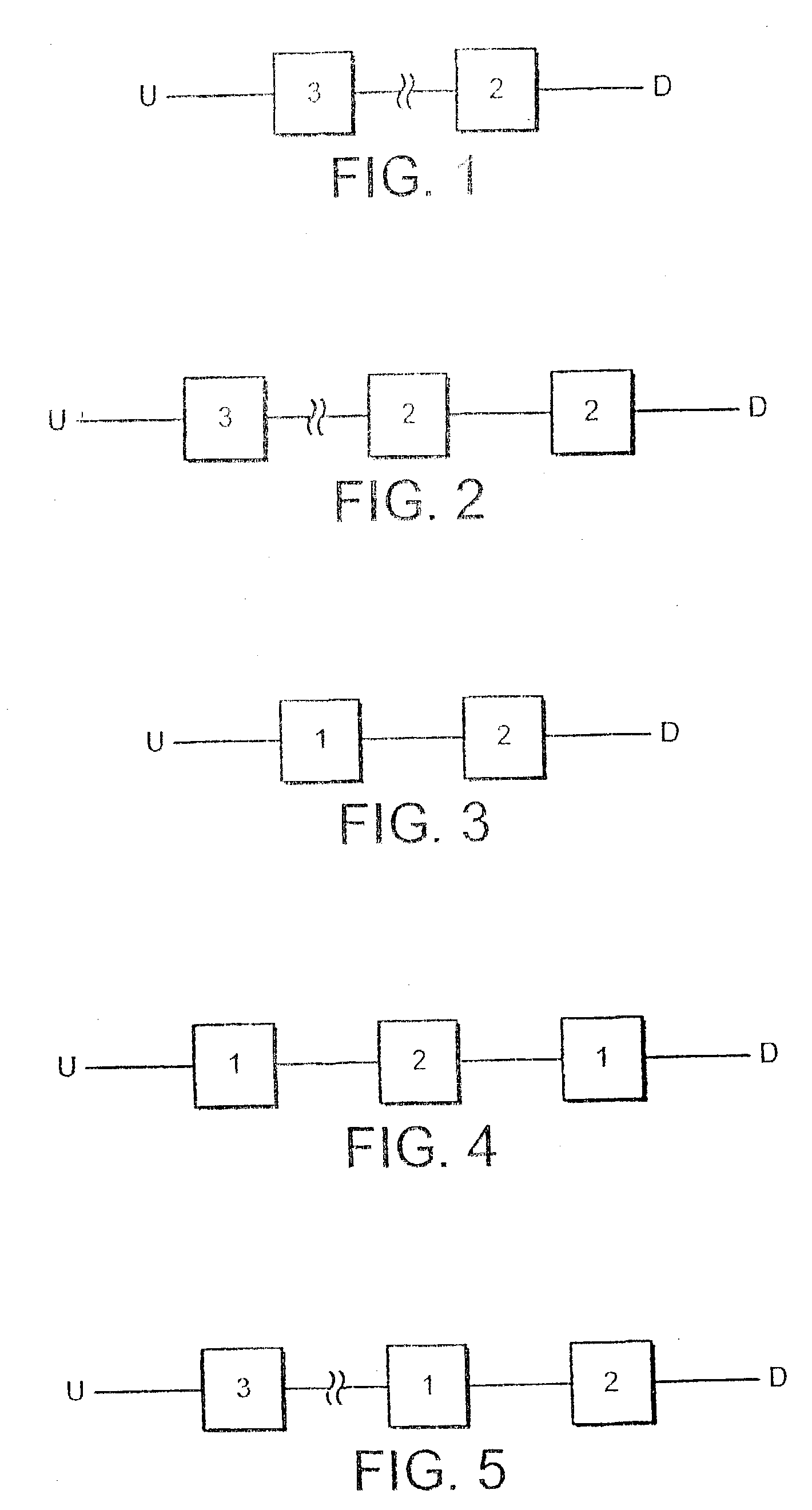
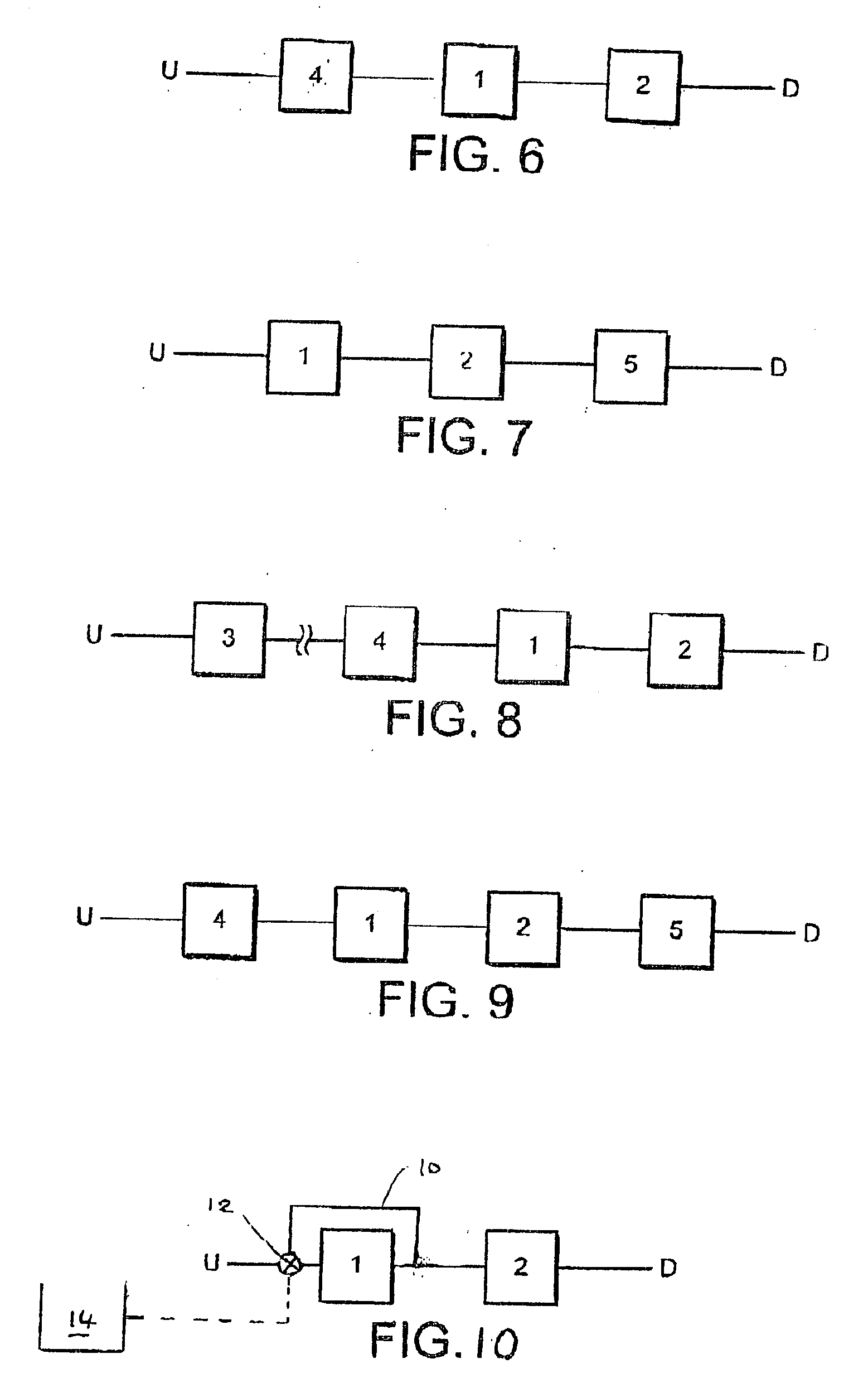
0023] We have now found that, very surprisingly, HC aftertreatment can be improved for lean-burn engines if an oxidation catalyst is included in the exhaust system upstream of a NO.sub.x-trap. In one embodiment of the invention, a lean-burn gasoline engine comprises an exhaust system having a first oxidation catalyst for oxidizing engine-derived, unburned hydrocarbons during .lambda.>1 conditions, and a NO.sub.x-trap downstream of the oxidation catalyst.
0024] According to another embodiment, the invention provides a lean-burn gasoline engine comprising an exhaust system, which system comprises a first oxidation catalyst for oxidizing unburned hydrocarbon (HC) during .lambda.>1 conditions, a NO.sub.x-trap downstream of the oxidation catalyst, by-pass means arranged between an upstream end and a downstream end of the NO.sub.x-trap and means for switching at least some exhaust gas flowing in the exhaust system to flow in the bypass during rich- or stoichiometric-running conditions, thereby substantially to prevent bypassed exhaust gas from contacting the oxidation catalyst.

Problems solved by technology

The main problem with the proposed system is its ability to deal with the relatively high levels of HC when running lean.
Meeting future legislation requirements for lean-bum engines in general, and lean-bum gasoline engines in particular, is difficult with respect to HC.

Method used


Image

  • Lean-burn gasoline engine including exhaust system therefor
  • Lean-burn gasoline engine including exhaust system therefor
  • Lean-burn gasoline engine including exhaust system therefor

Examples


Embodiment Construction

[0056] Apparatus

[0057] In a bench test cell, a 4 cylinder, 1.8-liter, 1997 model year, Mitsubishi direct injection engine from a vehicle calibrated for the Japanese market was installed with a direct current dynamometer. The original engine control unit (ECU) was disconnected and control of the engine was by an engine management and control system (EMACS). This was done so that an engine control strategy suitable for use with NO.sub.x-trap technology could be applied to the exhaust system for the purposes of our study. In particular, EMACS enabled complete control over ignition and injection timing and duration in both homogenous and lean-bum combustion modes.

[0058] The engine was operated from one of two sets of maps: one for the homogeneous mode and the other for the lean mode. Basic maps for ignition and injection timing and duration were generated by firstly logging data from the ECU of a vehicle including the same model of engine as the one used for the bench test and then basi...


PUM

PropertyMeasurementUnit
thicknessaaaaaaaaaa
thicknessaaaaaaaaaa
inlet temperatureaaaaaaaaaa

Abstract

A lean-burn gasoline engine including an exhaust system, which system has a first oxidation catalyst for oxidizing engine-derived, unburned hydrocarbons during lambda>1 conditions, and a NOx-trap downstream of the oxidation catalyst. Also included in one embodiment is by-pass means arranged between an upstream end and a downstream end of the oxidation catalyst and means for switching at least some exhaust gas flowing in the exhaust system to flow in the bypass during rich or stoichiometric running conditions, thereby substantially to prevent bypassed exhaust gas from contacting the oxidation catalyst. Included in the invention are methods of treating the exhaust gas streams with the apparati defined above.

Description

CROSS-REFERENCE TO RELTAED APPLICATIONS[0001] This application is a National Phase Application of, and a Continuation-in-Part Application of, PCT / GB01 / 03840, which claimed the benefit of Great Britain Application No. 0021118.5 filed Aug. 29, 2000.[0002] The present invention relates to a lean bum gasoline engine comprising an exhaust system and in particular to a lean bum gasoline engine wherein the exhaust system comprises a NO.sub.x-trap.[0003] Manufacturers are increasingly interested in engines which operate under lean-running conditions to power their vehicles. One reason for this is because lean-bum engines produce less CO.sub.2. This is advantageous because future emission legislation aims to reduce CO.sub.2, but the consumer also benefits from the increased fuel economy.[0004] One form of lean-bum engine is a gasoline direct injection engine, which is designed to operate under stoichiometric and lean conditions. When running lean, relatively low levels of nitrogen oxides (NO...

Claims


Application Information

Patent Timeline
Patent Type & Authority Applications(United States)
IPC IPC(8): F01N3/28B01D53/94F01N3/08F01N3/10F01N13/02
CPCF01N3/0814F01N3/0835F01N3/0842F01N3/085F01N13/0093F01N2570/16Y02T10/22Y02T10/24F01N13/009F01N2250/12Y02T10/12F01N3/20
Inventor BRISLEY, ROBERT JAMESSWALLOW, DANIELTWIGG, MARTYN VINCENT
Owner JOHNSON MATTHEY PLC
Why Eureka
Try Eureka