
Combined printing machine

a combined printing machine technology, applied in the field of printing machines, can solve the problems of insufficient sheet retention through electrostatic charges, inconvenient transportation of sheets, and inconvenient storage of sheets on conveyor belts

Inactive Publication Date: 2003-12-04
MANROLANAD AG
View PDF4 Cites 1 Cited by
  • Summary
  • Abstract
  • Description
  • Claims
  • Application Information

AI Technical Summary

Benefits of technology

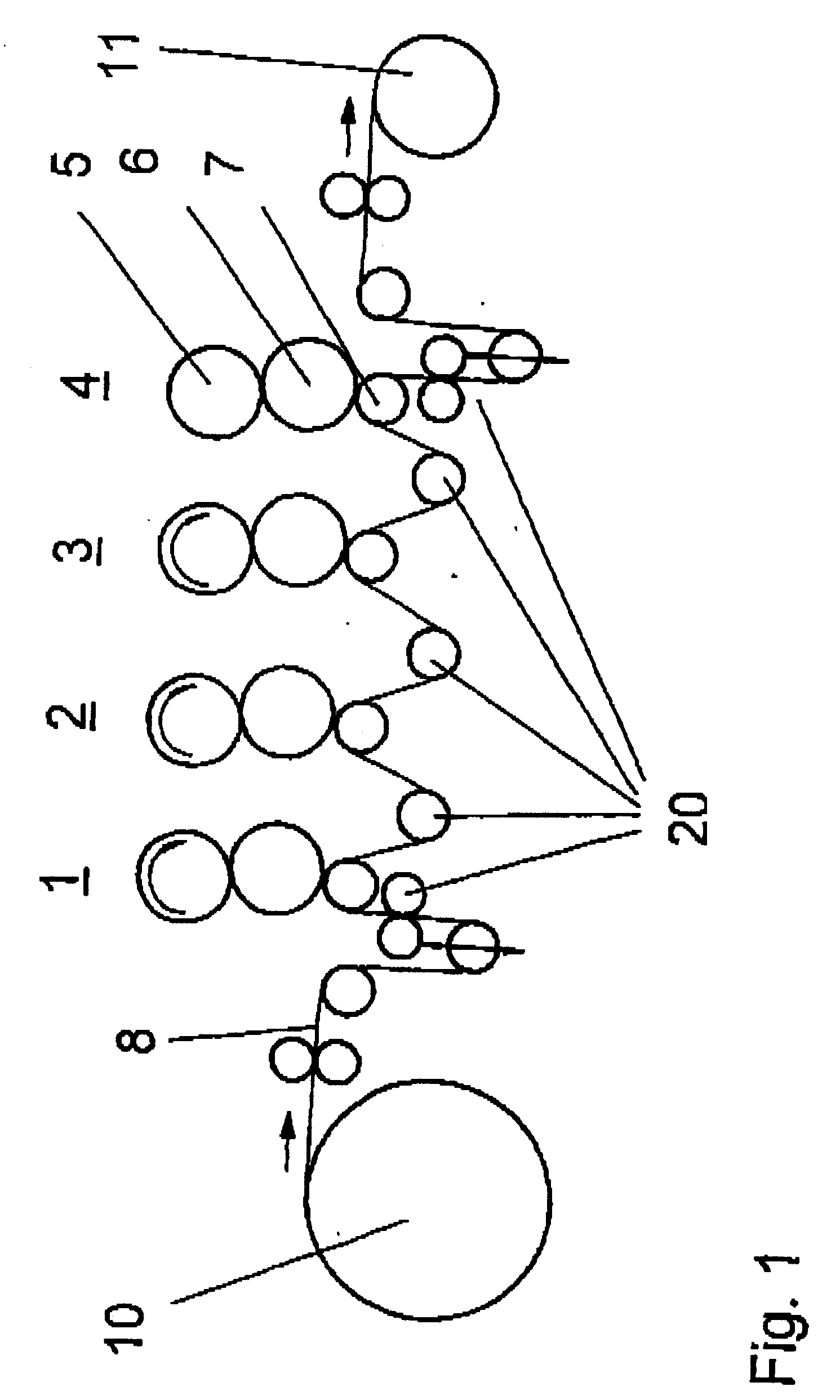
[0016] This means that the described printing machine consists of an offset printing machine. However, the printing machine according to FIG. 1 does not contain so-called blanket-to-blanket printing units. In this case, each printing unit 1-4 is respectively provided with an impression cylinder 7 that merely serves to press the printable matter against the printing cylinder, in this case, the blanket cylinder 6. Such a simple configuration of a web-fed rotary printing machine has not been disclosed thus far because the printing units 1-4 usually are always equipped for a double-sided printing process. For reasons of simplicity, the impression cylinders 7 have a smaller diameter than the blanket cylinders 6 and the plate cylinders 5. This is possible because each impression cylinder 7 merely fulfills a support function. The proper registration of the print images in the various printing units 1-4 can be realized with the aid of deflection rollers 20 or other devices, e.g., so-called web tensioning devices.
[0007] This objective is attained with the characteristics disclosed in the characterizing portion of claim 1. The machine configuration makes it possible to transport printable matter that may vary broadly with respect to shape, size and material composition. In this case, renewable holding regions are preferably provided on a conveyor belt as the holding means for sheet-like printable matter. This makes it possible to always realize the same conditions for all sheets to be transported through the printing machine. In addition, it is no longer necessary to generate electrostatic charges. This device is also suitable for various types of printable matter. Advantageous embodiments of the invention are described in the dependent claims, and pertain to holding means in the form of adhesive films, melt-on adhesive regions, variably applicable adhesive strips, offset pressing devices, rolling devices, or timed transport movements of the rollers.

Problems solved by technology

However, this publication contains no information regarding retention of the sheets on the conveyor belt with correct registration.
This publication also contains a reference to the fact that retention of the sheet by means of electrostatic charges is not sufficient for transport of the sheets.

Method used


Image

  • Combined printing machine
  • Combined printing machine
  • Combined printing machine

Examples


Embodiment Construction

[0008] The invention is described in greater detail below, with reference to the figures.

[0009] The figures show:

[0010] FIG. 1, a web-fed rotary printing machine of standard configuration,

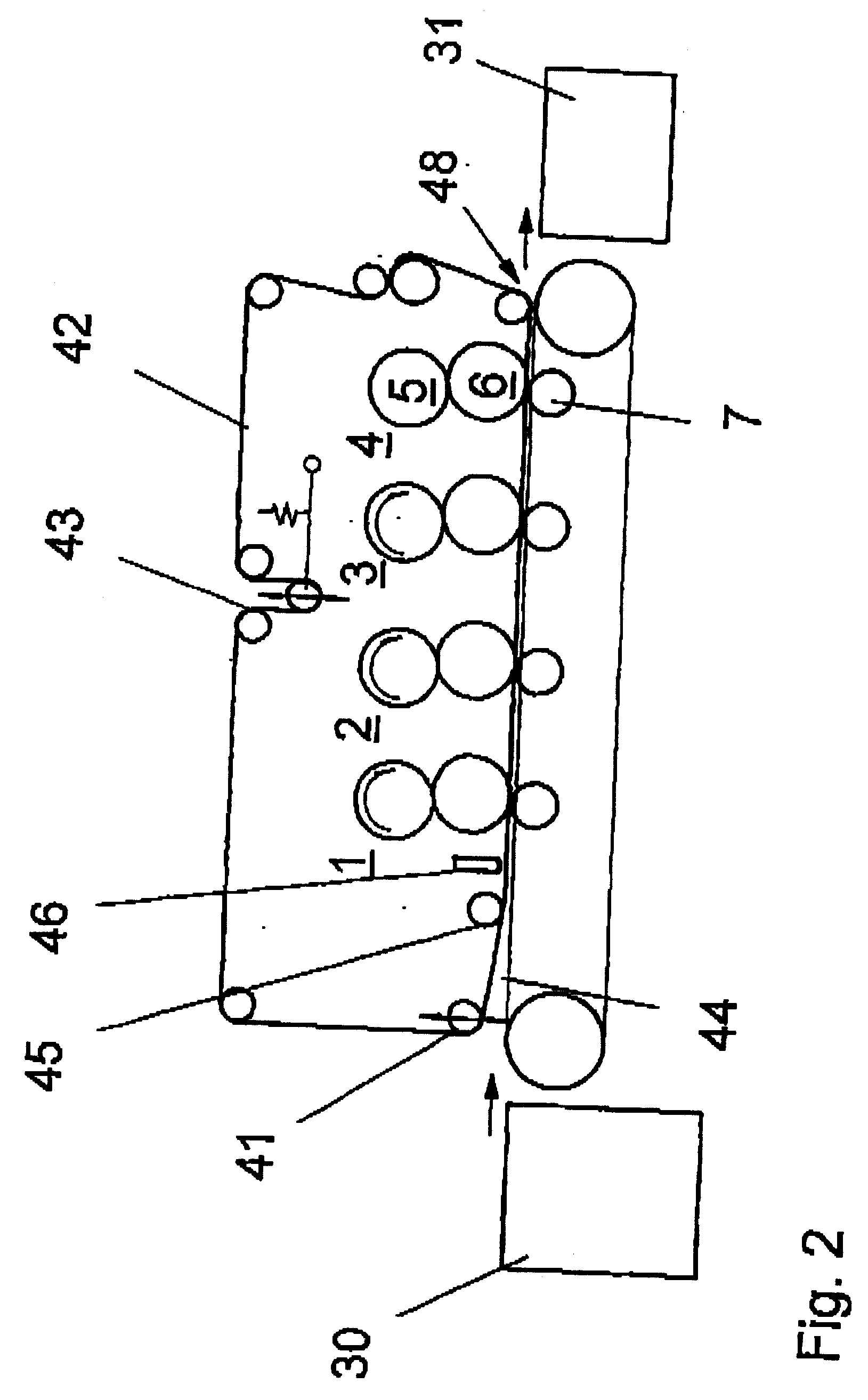
[0011] FIG. 2, a printing machine of the same configuration with a conveyor belt and holding bands,

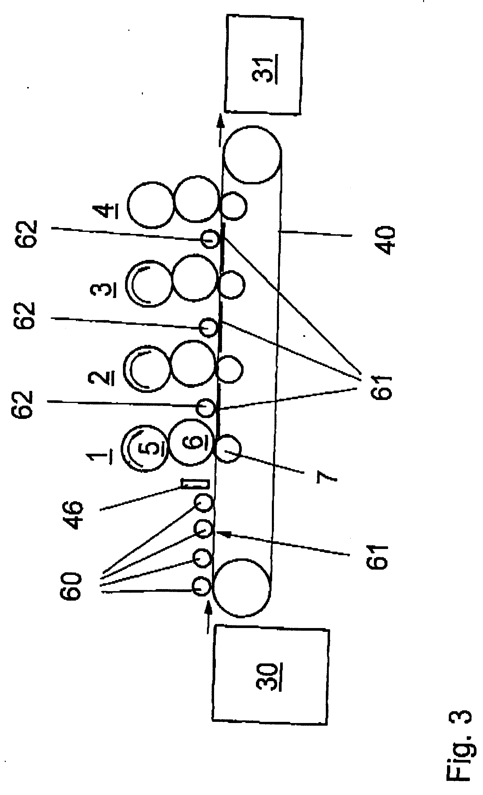
[0012] FIG. 3, a printing machine of the same configuration with a conveyor belt and pressing rollers,

[0013] FIG. 4, a printing machine of the same configuration with a conveyor belt and a pneumatic pressing device, and

[0014] FIG. 5, a top view of a printing machine according to FIG. 2.

[0015] FIG. 1 shows a web-fed rotary printing machine with several printing units 1-4, the basic configuration of which comprises an impression cylinder 7, a blanket cylinder 6 and a plate cylinder 5. The web 8 of printable matter is unwound from a supply roll 10 and transported to the impression cylinder 7 of the printing unit 1, with the web being printed in this printing unit by means of the blanket cylinder 6 and th...


PUM


Abstract

The invention relates to a printing machine for multicolour printing, in which all printing units are configured in the same manner. Said machine is provided with a feed system for printable matter, which is suitable for both sheet-type and web-type printable matter. The printable matter can be connected to the feed system for printable matter in correct alignment and transported through all printing units (1-4) of the printing machine, using appropriate devices. The machine is provided with a transport belt, as the feed system for printable matter. Said belt is fed in a straight line through all the printing zones of the printing units (1-4) and is assigned to the printing cylinders (7). The transport belt can be attached to the printable matter by means of adhesion, contact pressure, application or using retaining strips.

Description

DESCRIPTION[0001] The invention pertains to a device according to the preamble of claim 1.PRIOR ART[0002] In printing machines for various printing methods, it is common practice to provide sheet transport means that allow a linear transport of substrates to be printed through the printing units from the feed station to the delivery station. Some of these methods and devices utilize grippers. Other methods and devices utilize conveyor belts that are linearly guided through the printing units for transporting the sheet-like materials.[0003] DE 19527264 A1 discloses a printing machine with a linear substrate guide. In this case, the transport path of the substrates should extend linearly from the feed stack to the transport means in the plane of the transport path through the printing units. A conveyor belt is provided which transports the substrates between the cylinders of the printing units, e.g., by means of a frictional engagement. However, this publication contains no informatio...

Claims


Application Information

Patent Timeline
IPC IPC(8): B41F21/00B65H23/28
CPCB41F21/00
Inventor SCHNEIDER, JOSEFDILLING, PEER
Owner MANROLANAD AG
Learn More