
Measurement technique for a radio access telecommunications terminal

Inactive Publication Date: 2003-12-11
LENOVO INNOVATIONS LTD HONG KONG
View PDF8 Cites 24 Cited by
  • Summary
  • Abstract
  • Description
  • Claims
  • Application Information

AI Technical Summary

Benefits of technology

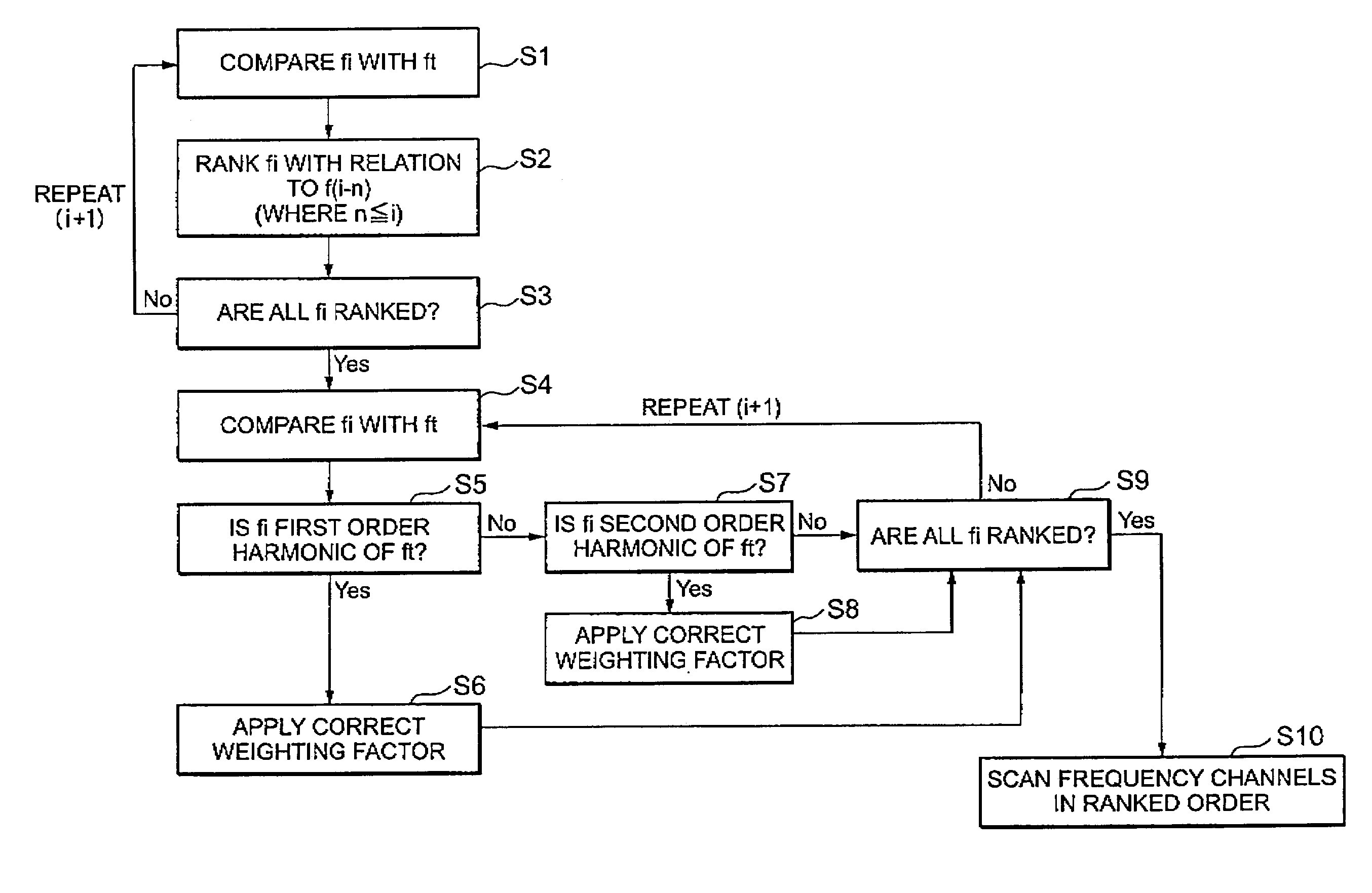
[0008] The present invention reduces the power consumed in a dual mode user equipment (UE) terminal by reducing the amounts of interference on a measured down link signal. By reducing the interference, the number of remeasurements of down link channels and retransmission of data is reduced and consequently the amount of power consumed by the UE is also reduced, therefore increasing battery life.
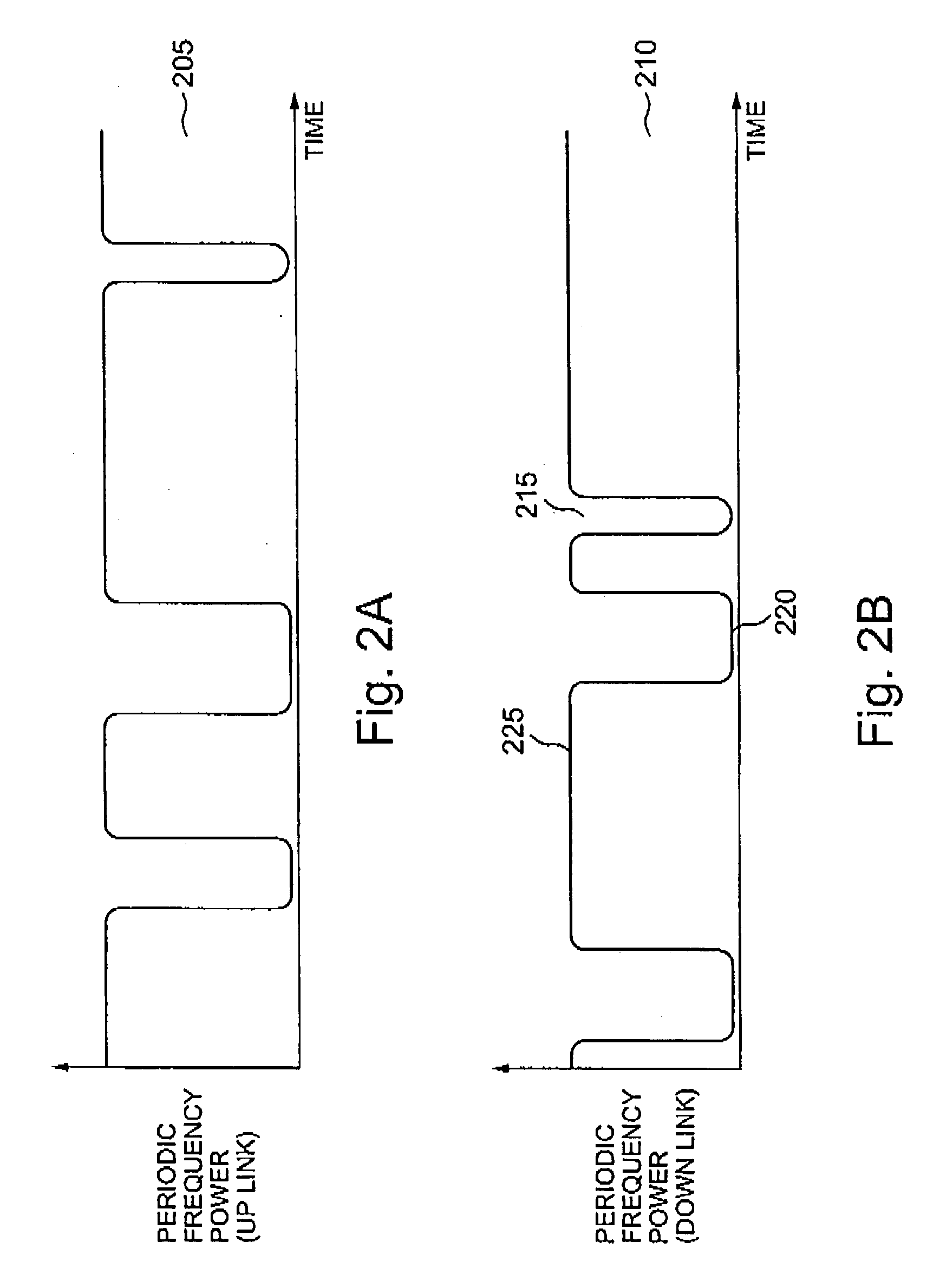
[0012] Additionally, the amount of interference on the second type down link signal being measured is further reduced by ordering the sequence in which the down link signals are measured, with the most interfering signals being ordered so that measurement of these occurs at a point during a reduced power mode of the UE transmitter, furthest from the peak power level of the UE transmitter.

Problems solved by technology

Therefore, unlike the Global System of Mobile communications (GSM) standard, there is no discrete time slot allowed for the UE to measure the strength of other frequency channels.
However, this means that if the UE switches the GSM measurement receiver on too early, i. e. before the UMTS transmitter is "powered down", the GSM receiver may cause internal interference on the UMTS signal that is being transmitted, and therefore repeated data transmission may be required.
Accordingly, this increases power consumption.
Additionally, if the measurements made by the GSM measurement receiver are carried out at the start of the compressed mode gap, if the UMTS transmitter is not fully powered down, interference can occur on the GSM measured signal, and therefore repeated measurements of the GSM signal may be required.
This again increases power consumption within the UE.

Method used


Image

  • Measurement technique for a radio access telecommunications terminal
  • Measurement technique for a radio access telecommunications terminal
  • Measurement technique for a radio access telecommunications terminal

Examples


Embodiment Construction

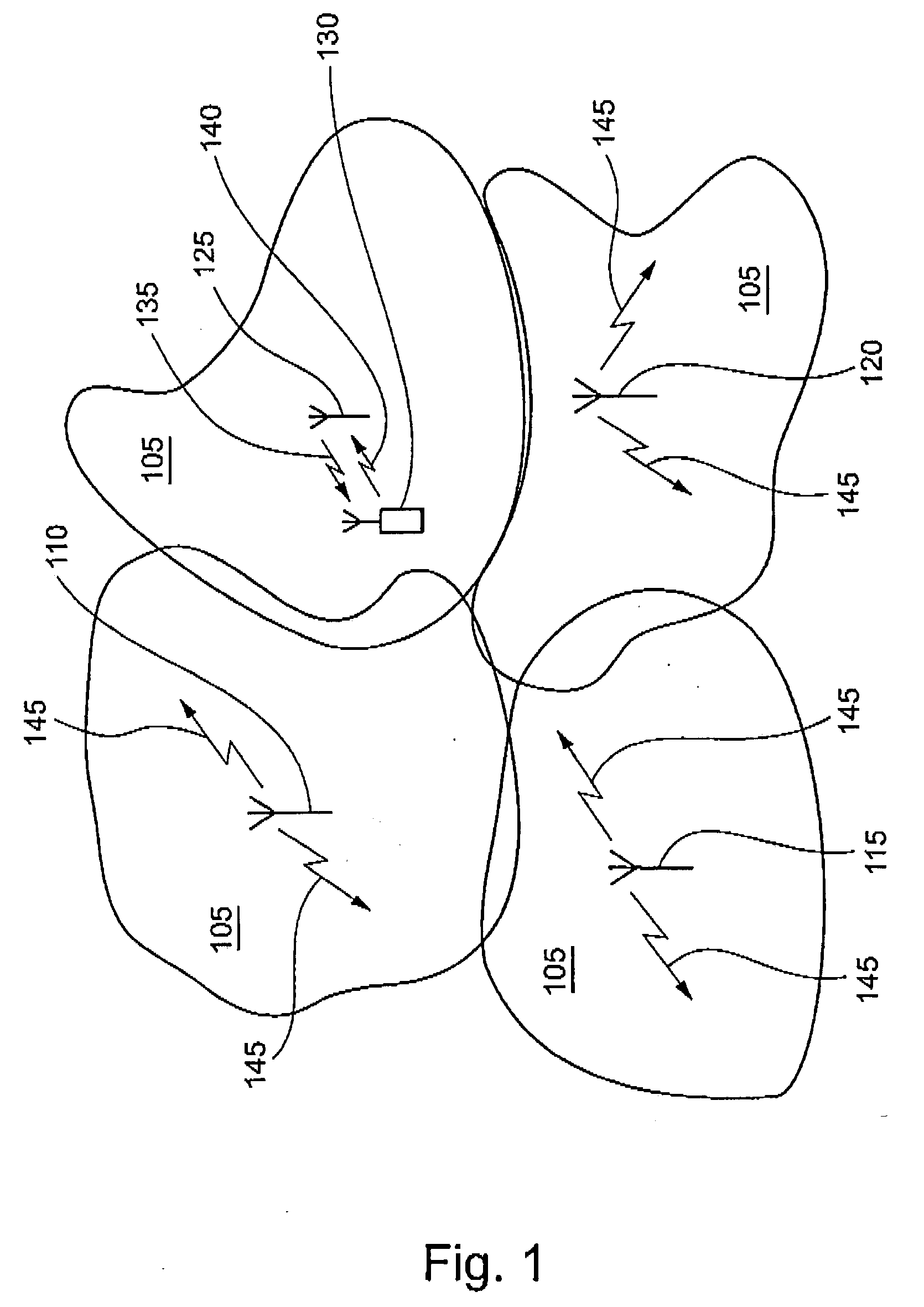
[0022] FIG. 1 shows a perspective view of four communication cells 105. Each of the communication cells 105 is generated by a first, second, third and fourth base station 110, 115, 120, 125 respectively. The cells 105 define an area, in which user equipment (UE) can communicate with one of the appropriate base stations 110, 115, 120, 125. In FIG. 1, a UE 130 is in communication with the fourth base station 125. Clearly, although only a single UE 130 is shown communicating with the fourth base station 140, it is understood that in reality, the fourth base station may be in communication with several UEs 130. The UE 130 generates an "up link" signal 140 which is transmitted to and received by the fourth base station 125. The fourth base station 125 communicates with the UE 130 by generating a "down link" signal 135 which is received, and processed, by the UE 130. It should be noted that in this embodiment, the mobile station is capable of generating the up link signal in accordance wi...


PUM


Abstract

A frequency division duplex radio access telecommunications terminal comprises a transmitter for transmitting a transmission signal at a first frequency. The transmitter is arranged to switch between a peak power mode in which the transmission signal is transmitted at a peak power level, and a reduced power mode. A receiver receives a reception signal at a second frequency different from the first frequency. A detector measures the signal strength of the reception signal. A controller is arranged to cause the detector to measure the signal strength of the reception signal whilst the transmitter is operating in the reduced power mode, and at a predetermined time before the transmitter switches to the peak power mode.

Description

[0001] The present invention relates to the field of frequency division duplex radio access telecommunication terminals and in particular to the measurement of the received signal strength of frequency channels within a transmission gap.BACKGROUND OF INVENTION[0002] In the Universal Mobile Telecommunications Standard (UMTS) air interface, a base station communicates with User Equipment (UE) continuously. Therefore, unlike the Global System of Mobile communications (GSM) standard, there is no discrete time slot allowed for the UE to measure the strength of other frequency channels. However, the UMTS standard has defined periods in this continuous transmission where the transmitter and receiver within the UE are "powered down". These gaps are defined as the compressed mode, and as such the UE has the opportunity of making measurements of the received signal strength on other frequency channels. It the received signal strength on a different channel is stronger, the UE changes channel ...

Claims


Application Information

Patent Timeline
IPC IPC(8): H04J1/00H04B7/26H04J7/00H04W36/14H04W36/30H04W88/06
CPCH04W36/0083Y02B60/50H04W88/06H04W24/10H04W36/0085Y02D30/70
Inventor FALAKI, HAMID
Owner LENOVO INNOVATIONS LTD HONG KONG
Learn More