

Continuous transesterification process
a transesterification process and process technology, applied in the field of biodiesel, to achieve the effect of facilitating the transesterification reaction and high shear
- Summary
- Abstract
- Description
- Claims
- Application Information
AI Technical Summary
Benefits of technology
Problems solved by technology
Method used
Image

Examples
example 9
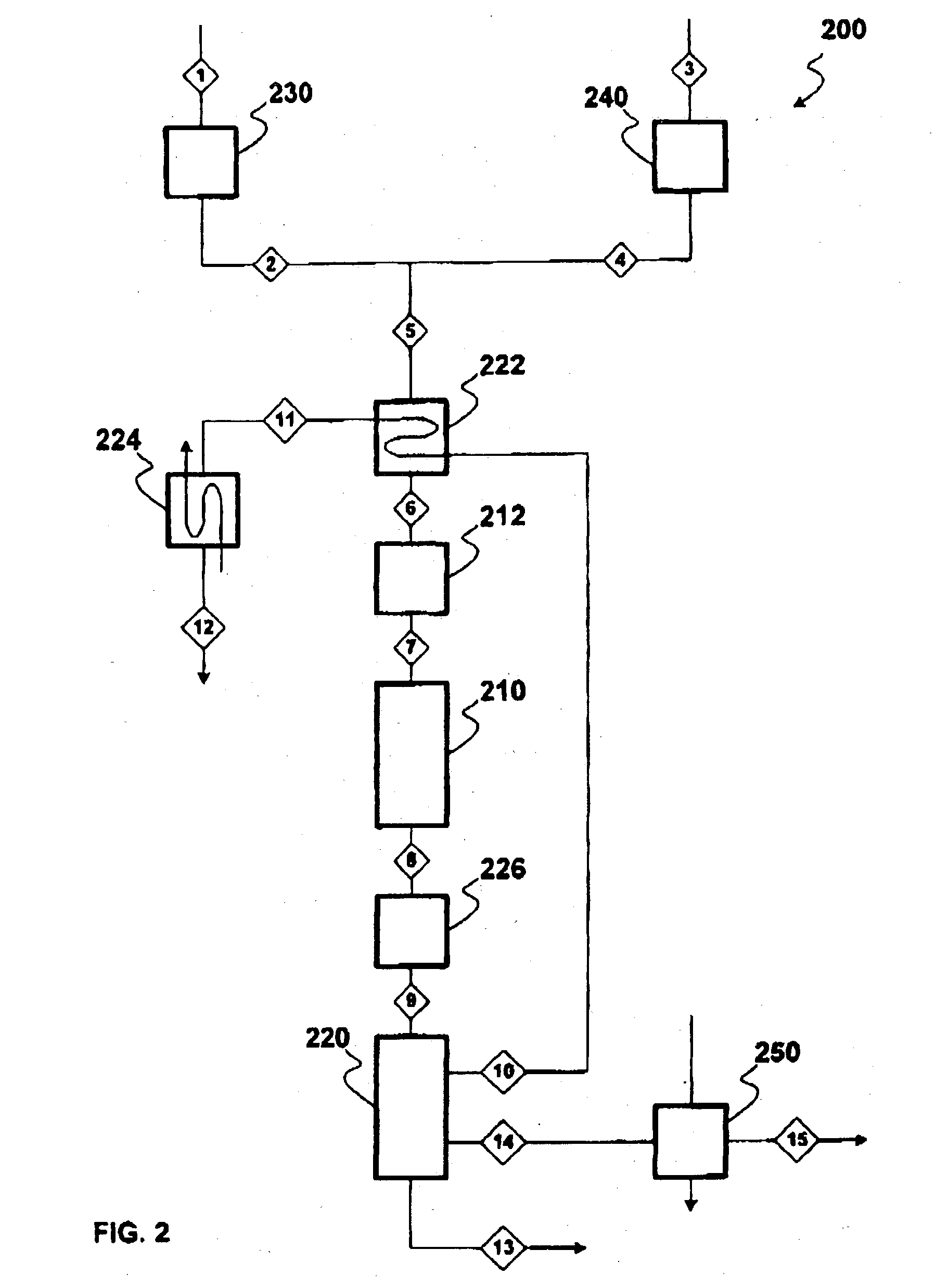
[0044] Reference is made to FIG. 2. In Example 9, Table 2 is a stream table, which depicts processing conditions and results.
2TABLE 2 Processing Conditions for Conversion of Triglycerides to Methyl Esters Stream No. 1 2 3 4 5 6 7 8 T, .degree. F. 70 70 70 70 65 100 302 314 P, psia 25 230 25 250 250 250 250 240 M, lb / hr 2,400 2,400 10,200 10,200 12,600 12,600 12,600 12,600 Wt., pct Triglycerides 100 100 80.93 80.93 80.93 0.4 MeEsters 80.9 MeOH 95.75 95.75 18.26 18.26 18.26 9.57 NaOH 4.25 4.25 0.81 0.81 0.81 0.81 Glycerol 8.32 Table 2 - Continued Stream No. 9 10 11 12 13 14 15 T, .degree. F. 356 355 320 122 355 355 n / a P, psia 240 29 29 29 29 29 n / a M, lb / hr 12,600 1,460 1,460 1,460 950 10,200 n / a Wt., pct Triglycerides 0.4 3.49 3.49 3.49 0.27 MeEsters 80.9 0.45 0.45 0.45 99.7 MeOH 9.57 80.57 80.57 80.57 2.32 NaOH 0.81 8.26 Glycerol 8.32 8.55 8.55 8.55 89.4
[0045] In one embodiment, processing conditions for Example 9 include a tube as the plug-flow reactor 210. The tube is a packed pi...
PUM
 Abstract
Description
Claims
Application Information