Magnetic random access memory

a random access and memory technology, applied in the field of magnetic random access memory, can solve the problems of reducing the effect, affecting the correct detection of the resistance of the memory cell,

Inactive Publication Date: 2004-01-08
NEC CORP
View PDF2 Cites 116 Cited by
  • Summary
  • Abstract
  • Description
  • Claims
  • Application Information

AI Technical Summary

Problems solved by technology

The sneak path electric current hinders the correct detection of the resistance of the memory cell when the data stored in the memory cell is determined.
However, it is difficult in practice to coincide the operation voltage Vb with the operation voltage Vs totally.
The difficulty to coincide the operation voltage Vb and the operation voltage Vs totally decreases the effect of the restraint of the influence of the sneak path electric current.

Method used


Image

  • Magnetic random access memory
  • Magnetic random access memory
  • Magnetic random access memory

Examples


first embodiment

[0074] (First Embodiment)

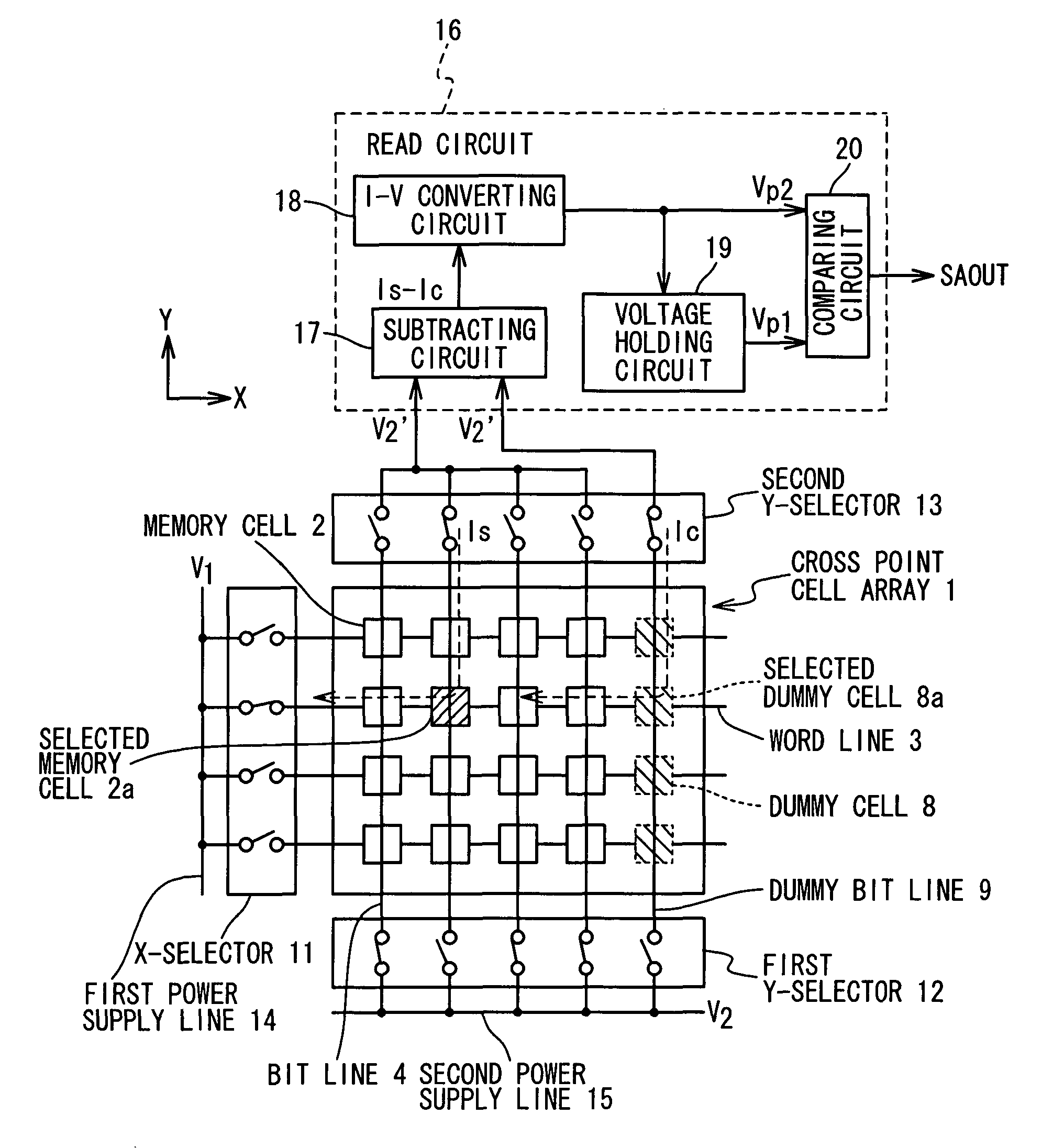
[0075] The magnetic random access memory according to the first embodiment of the present invention is composed of a cross point cell array 1 as shown in FIG. 4. The cross point cell array 1 contains a plurality of memory cells 2, a plurality of word lines 3 extending into the X-direction (row direction) and a plurality of bit lines 4 extending into a Y-direction (column direction). The memory cell 2 is arranged in the intersection of the word line 3 and the bit line 4.

[0076] As shown in FIGS. 5A and 5B, each of the memory cells 2 contains a magnetic tunnel junction (MTJ) which is composed of a pin layer 5, a free layer 6 and a tunnel barrier layer 7 interposed between the pin layer 5 and the free layer 6. The pin layer 5 is connected with the word line 3 and the free layer 6 is connected with the bit line 4. The pin layer 5 and the free layer 6 contain ferromagnetic layers with spontaneous magnetization. The spontaneous magnetization of the pin layer 5 is f...

second embodiment

[0117] (Second embodiment)

[0118] FIG. 10 shows the magnetic random access memory of the second embodiment. In the second embodiment, the cross point cell array 1 of FIG. 4 is added with reference cells 31 and a reference dummy cell 32 which are arranged in line in the X-direction (the direction of the word line), and a reference word line 33 extending into the X-direction (the direction of the word line). Such a cross point cell array 1 is hereinafter referred to as a cross point cell array 1'.

[0119] The reference cells 31 and the reference dummy cell 32 have the same structure as either of the memory cells 2. Each of the reference cells 31 and the reference dummy cell 32 contains a magnetic tunnel junction which is composed of a pin layer, a free layer, and a tunnel barrier layer interposed between the pin layer and the free layer.

[0120] A predetermined data such as "0" is stored in the reference cell 31 which is used for the determination of the data in case of a read operation. H...

third embodiment

[0144] (Third Embodiment)

[0145] As descried above, in the magnetic random access memories shown in FIGS. 4, 9, 10 and 13, it is impossible to read data from the memory cell 2 which is connected with the same bit line as a short-circuited cell when the short-circuited cell exists in the cross point cell array 1 (or 1'). However, the existence of the short-circuited cell does not have any influence on the read operation of the memory cell 2 which is connected with the same word line as the short-circuited cell. Such a characteristic makes the redundant design easy in which the fault cell column containing the short-circuited cell is substituted by a redundant cell column of redundant memory cells. The redundant design is adopted for the magnetic random access memory in the third embodiment.

[0146] FIG. 14 shows the magnetic random access memory in the third embodiment. The magnetic random access memory in the third embodiment is composed of a plurality of cross point cell arrays 41 arr...


PUM


Abstract

In a magnetic random access memory, a cross point cell array of memory cells is arranged in a matrix of columns and rows, and each of the memory cells has a magneto-resistance element. A column of dummy memory cells is provided, and each of the dummy memory cells has a magneto-resistance element. Word lines are provided for the rows of the memory cells and the dummy memory cells, respectively, and bit lines are provided for the columns of the memory cells, respectively. A dummy bit line is provided for the column of dummy memory cells. A read circuit is connected with the cross point cell array and the dummy bit line.

Description

[0001] 1. Field of the Invention[0002] The present invention relates to a magnetic random access memory (MRAM), especially to a technique to determine more surely data stored in a memory cell of MRAM.[0003] 2. Description of the Related Art[0004] A magnetic random access memory (MRAM) collects attention as a new nonvolatile memory that it is possible a high-speed writing operation and the number of times of rewrite is large. A typical MRAM contains a memory cell array in which a plurality of memory cells are arranged in a matrix. Each memory cell contains a magnetoresistance device which is composed of a pin layer having fixed spontaneous magnetization, a free layer having spontaneous magnetization whose direction can be inverted, and a spacer layer interposed between the pin layer and the free layer.[0005] The free layer is formed such that the direction of the spontaneous magnetization of the free layer can be set to a same direction (hereinafter, to be referred to as a parallel d...

Claims


Application Information

Patent Timeline
Patent Type & Authority Applications(United States)
IPC IPC(8): G11C11/15H01L21/8246H01L27/10H01L27/105H01L43/08
CPCG11C11/15
Inventor SAKIMURA, NOBORUHONDA, TAKESHISUGIBAYASHI, TADAHIKO
Owner NEC CORP
Why Eureka
Try Eureka