
Underwater cable arrangements and devices

a cable arrangement and cable technology, applied in repeater circuits, line-transmission details, instruments, etc., can solve the problems of water entering the interior of the cable, battery life is limited, battery must be replaced, battery has a number of serious drawbacks,

Inactive Publication Date: 2004-01-15
INPUT OUTPUT INC
View PDF8 Cites 9 Cited by
  • Summary
  • Abstract
  • Description
  • Claims
  • Application Information

AI Technical Summary

Benefits of technology

"The invention is about an underwater cable arrangement that includes external devices such as depth control mechanisms, acoustic ranging devices, and magnetic heading sensors. These devices can be powered by a coil within the cable, eliminating the need for batteries and reducing the risk of leakage and damage to the cable. The external devices can also be easily removed and reattached without stopping the deployment and retrieval of the cable, saving time and storage space. The invention provides an improved and more efficient way to power and protect external devices on underwater cables."

Problems solved by technology

It is possible to connect such external devices with a source of power aboard the towing vessel by means of wires passing through the skin of the cable, but the necessity of forming holes in the skin for the wires can lead to leakage of water into the interior of the cable, which is highly undesirable.
However, batteries have a number of serious drawbacks.
First, the batteries have a limited life span and must be replaced every one to three months.
Not only is the replacement of the batteries time-consuming, there is also the risk of exposing electric circuitry within the external device to sea water during replacement.
In addition, lithium primary batteries, which are used because of their longer operating life compared to other batteries, are expensive, and spent batteries must be retained for proper disposal and not randomly discarded.
Furthermore, each time the cable is reeled in to replace batteries in the external devices, it is subjected to stresses which frequently result in damage to the cable.
In rough seas, it can be extremely difficult and often dangerous for workers to remove the external devices from or reattach them to the cable on the deck of the towing vessel.
Furthermore, onboard storage space, often a precious commodity, must be provided for the external devices on board the towing vessel.
In addition, the reeling in or paying out of the underwater cable must be stopped during removal or reattachment of the external devices, so deployment and retrieval of the cable are time consuming.
Therefore, the load on any batteries in the external device is small, and the batteries can be used for long periods without requiring replacement.

Method used


Image

  • Underwater cable arrangements and devices
  • Underwater cable arrangements and devices
  • Underwater cable arrangements and devices

Examples


Embodiment Construction

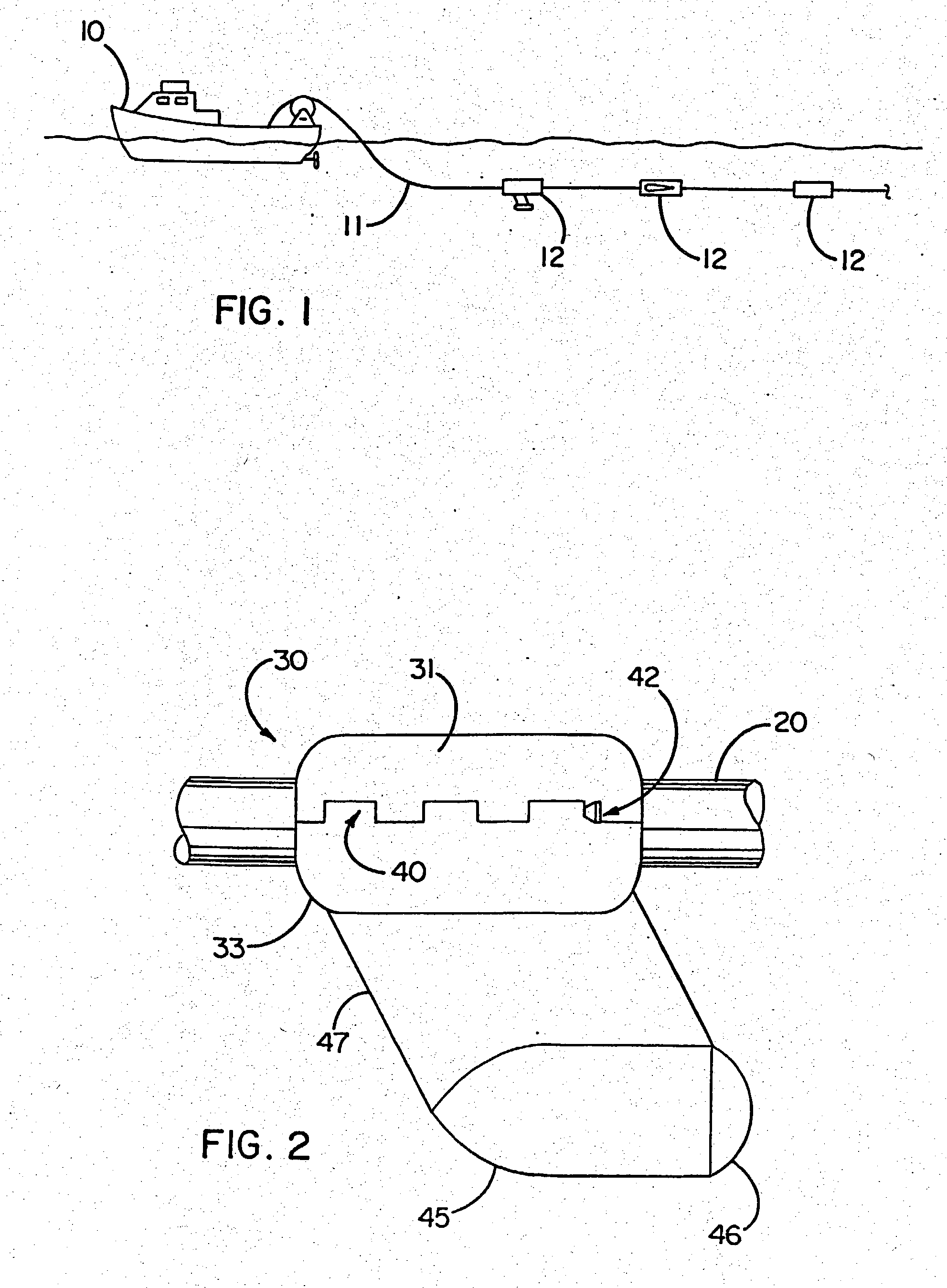
[0051] FIG. 1 schematically illustrates an example of an underwater cable arrangement according to the present invention. The arrangement includes an underwater cable 11 being towed through the water by a towing vessel 10, such as an ordinary surface vessel, although the cable 11 can also be towed by an underwater vessel or by an aircraft. One or more external devices 12 are attached to the underwater cable 11 at intervals along its length. For simplicity, only three external devices 12 ate illustrated, but there is no restriction on the number or type of devices which are attached to the cable 11. In addition, although only a single cable 11 is shown, the towing vessel 10 may tow a plurality of cables simultaneously.

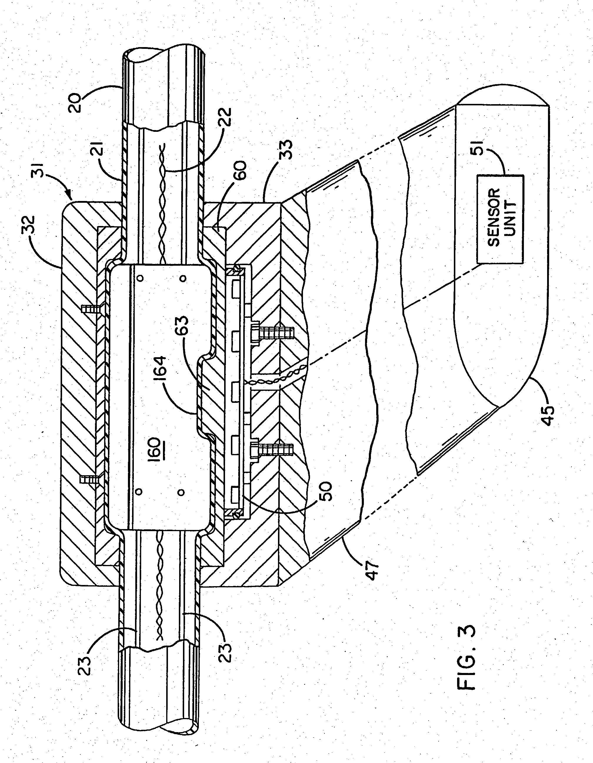
[0052] FIGS. 2 through 6 illustrate a first embodiment of an external device 30 which can be mounted on an underwater cable 20. FIGS. 2 and 3 show the external device 30 as it would appear when being towed through the water by the cable 20 to the left in the figures. Th...


PUM


Abstract

The present invention provides an underwater cable arrangement includes an underwater cable having one or more external devices mounted on the cable. In one form of the invention, the external devices are powered primarily or entirely by inductive coupling between a coil disposed in the cable and a coil disposed in the external device. The invention also provides a variety of external devices capable of use with an underwater cable. The invention further provides a coil support arrangement for supporting a coil within an underwater cable in a manner protecting a core of the coil from damage.

Description

REFERENCE TO RELATED APPLICATIONS[0001] This application is a divisional of U.S. application Ser. No. 09 / 551,832, filed on Apr. 18, 2000, which is a divisional of U.S. application Ser. No. 09 / 043,447, which issued as U.S. Pat. No. 6,091,670 on Jul. 18, 2000, and which is the United States National Stage of International Application No. PCT / US96 / 15478 filed on Sep. 20, 1996, which claimed the benefit of U.S. Provisional Application No. 60 / 004,203, filed on Sep. 22, 1995; U.S. Provisional No. 60 / 004,209, filed on Sep. 22, 1995; U.S. Provisional Application No. 60 / 004,493, filed on Sep. 22, 1995; U.S. Provisional Application No. 60 / 004,494, filed on Sep. 22, 1995; and U.S. Provisional Application No. 60 / 005,500, filed on Sep. 22, 1995, all of the above referenced provisional applications being incorporated by reference.[0002] This application also incorporates by reference the disclosure of U.S. patent application Ser. No. 09 / 043,458 by R. Rouquette, which is the United States National...

Claims


Application Information

Patent Timeline
Patent Type & Authority Applications(United States)
IPC IPC(8): G01V1/20G01V1/22G01V1/38H04B3/36H04B3/44
CPCG01V1/201G01V1/22H04B3/44H04B3/36G01V1/3826
Inventor OLIVIER, ANDRE W.ROUQUETTE, ROBERT E.RAU, BRIEN G.
Owner INPUT OUTPUT INC
Learn More