
Method and apparatus for MWD formation testing

a technology of formation testing and wireline tools, which is applied in the direction of survey, greenhouse gas reduction, borehole/well accessories, etc., can solve the problems of conventional such apparatus, time-consuming and costly, and laborious process known as "tripping"

Active Publication Date: 2004-01-22
HALLIBURTON ENERGY SERVICES INC
View PDF84 Cites 80 Cited by
  • Summary
  • Abstract
  • Description
  • Claims
  • Application Information

AI Technical Summary

Benefits of technology

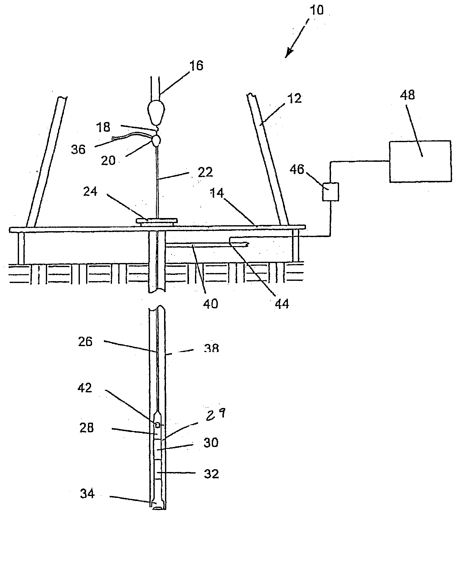
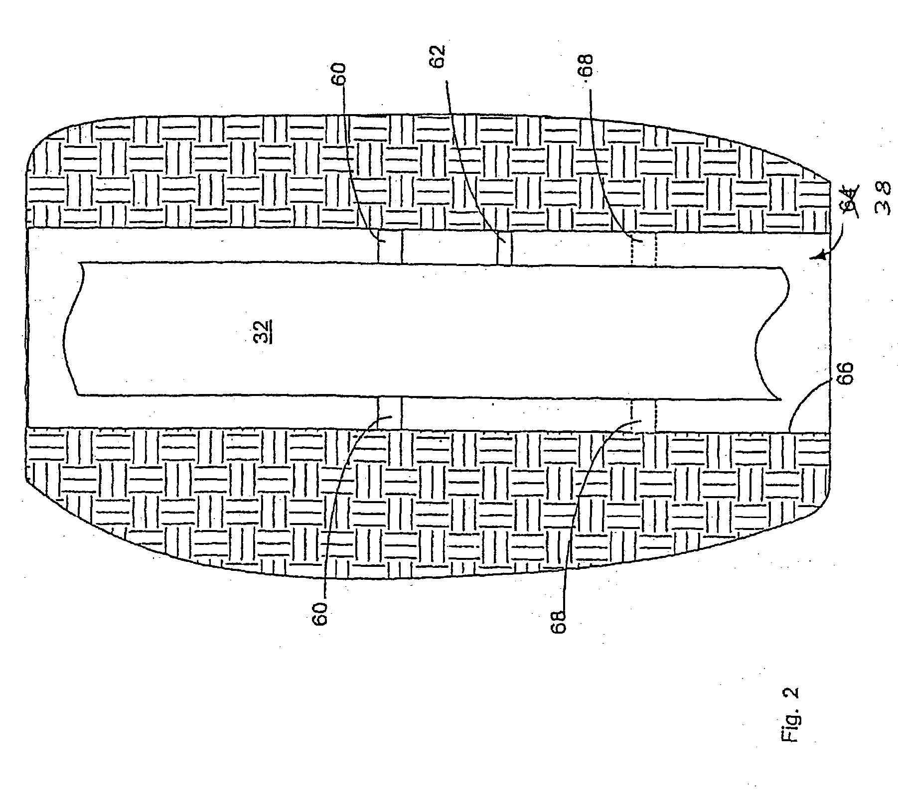
[0012] In accordance with the spirit of the present invention, a novel formation testing tool is described herein. One property of the present formation testing tool is that an extending probe or sample device contacts the borehole wall substantially normal to the wall, protecting the probe from excessive bending moments and other excessive forces.

Problems solved by technology

This process, known as "tripping" is a laborious and time consuming process by which the drill string, which may be miles long, is removed from the hole, pipe section by pipe section.
As well be understood, conducting formation tests via a wireline tool is time consuming and costly, given that costs of drilling a well may be thousands of dollars per hour.
However, there are various complications associated with conventional such apparatus.
When this occurs, without the flow of constantly moving drilling fluid, the bottom hole assembly can become stuck in the hole, necessitating a costly and time consuming procedure to free the stock tool.
In such tools, stopping the flow of drilling fluid therefore prevents the tool from generating the needed electrical power, and power to operate the formation tester must be supplied by other means, such as batteries which, in certain instances, may be less reliable or otherwise less desirable.
Other problems and shortcomings are associated with present day formation testers.
When this occurs, the extending probe may be subjected to detrimental loading as the piston extends and contacts the borehole.
When this occurs, the seal necessary for properly extracting and measuring formation fluid pressure is difficult, if not impossible, to achieve.

Method used


Image

  • Method and apparatus for MWD formation testing
  • Method and apparatus for MWD formation testing
  • Method and apparatus for MWD formation testing

Examples


Embodiment Construction

[0012] In accordance with the spirit of the present invention, a novel formation testing tool is described herein. One property of the present formation testing tool is that an extending probe or sample device contacts the borehole wall substantially normal to the wall, protecting the probe from excessive bending moments and other excessive forces.

[0013] Several embodiments are disclosed as being illustrative of the spirit of the invention. For example, in one embodiment, the formation testing tool includes a longitudinal body with a flowbore; a plurality of extendable centralizing pistons coupled to the body; an extendable sample device coupled to the body; and a centralizing hydraulic circuit configured to cause each of the plurality of centralizing pistons to extend at substantially the same rate. The centralizing pistons are extended at substantially the same rate to assist in positioning the extending sample probe such that it is substantially normal to the borehole wall. The c...


PUM


Abstract

A method and apparatus for formation testing is disclosed. In a preferred embodiment, a formation testing tool includes a longitudinal body with a flowbore; a plurality of extendable centralizing pistons coupled to the body; an extendable sample device coupled to the body; and a centralizing hydraulic circuit configured to cause each of the plurality of centralizing pistons to extend at substantially the same rate. The centralizing hydraulic circuit includes a series of flow control and pressure-determining valves configured to extend the centralizing pistons at substantially the same rate, and to help maintain stability in the hydraulic circuit in response to external pressures. In some embodiments, the extendable sample device is preferably configured to be recessed beneath a surface of the body in a first position and to extend beyond the surface in a second position. The extendable sample device is preferably extended to contact the borehole wall substantially normal to the wall, protecting the sample device from excessive bending moments and other excessive forces.

Description

[0001] The present application claims the benefit of U.S. Provisional Application Serial No. 60 / 381,258, filed May 17, 2002, entitled Method and Apparatus for MWD Formation Testing, which is hereby incorporated herein by reference.[0002] Not applicable.[0003] 1. Field of the Invention[0004] This invention relates generally to a method and apparatus utilized in hydrocarbon exploration. More specifically, the invention relates to formation testing tools. Even more particularly, the present invention is directed to methods and apparatus for performing formation testing while drilling.[0005] 2. Background and Related Art[0006] Geologists and geophysicists are interested in the characteristics of the formations encountered by a drill bit as it is drilling a well for the ultimate production of hydrocarbons from the earth. Such information is useful in determining the correctness of the geophysical data used to choose the drilling location and in choosing subsequent drilling locations. In ...

Claims


Application Information

Patent Timeline
IPC IPC(8): E21B17/10E21B49/00E21B49/10
CPCE21B17/1014E21B49/10E21B49/008Y02E30/10E21B17/10E21B49/00
Inventor JONES, DALE ALLENMENCONI, JOHN R.FRANZEN, ANDREW T.
Owner HALLIBURTON ENERGY SERVICES INC
Learn More