Highly stable opto-mechanic switches

a switch and opto-mechanic technology, applied in the field of high-stable opto-mechanic switches, can solve the problems of not being widely adopted, affecting the performance of the switch, so as to achieve unprecedented stability and longevity against environment perturbations and wear-ou

Inactive Publication Date: 2004-01-22
AGILTRON
View PDF23 Cites 14 Cited by
  • Summary
  • Abstract
  • Description
  • Claims
  • Application Information

AI Technical Summary

Benefits of technology

0008] Accordingly, it is an object of the invention to provide a type of mechanical optical switch that utilizes compact optical elements and is insensitive to both angular variations and position shifts of the moveable light-guiding element. The present inventive mechanical optical switches therefore provide critical advantages of switching a light beam between an input fiber and output fibers with unprecedented stability and longevity against environment perturbations and wear-out.

Problems solved by technology

However, it has not been widely adopted because its lack of reliability and its high cost associated with its fabrication difficulty.
Consequently they have intrinsic drawbacks of polarization and wavelength dependences and induce signal distortions that become problematic as the channel count and transmission speed increase in the new generation network systems.
In an optical switch, light signal must be accurately entered into an optical fiber, or much of the signal strength will be lost.
For optical switches, alignment and maintenance of precision optical paths have been the main technical difficulty, since a slight misalignment can cause large insertion losses.
However, the use of individual collimator lenses disadvantageously increases the separation between adjacent fibers, resulting in the need for large beam displacement for light path switching.
Consequently, mechanical optical switches use individual fiber collimators have suffered from slow switching speeds and poor stability.
A disadvantage of Li's switch is that the beam propagations are no longer parallel rather with an angle.
This type of switch is therefore often very difficult and costly to make and its operation is less stable.
For the above reasons, current mechanical optical switches are expensive to produce and prone to fail with a short operation lifetime.

Method used


Image

  • Highly stable opto-mechanic switches
  • Highly stable opto-mechanic switches
  • Highly stable opto-mechanic switches

Examples


first embodiment

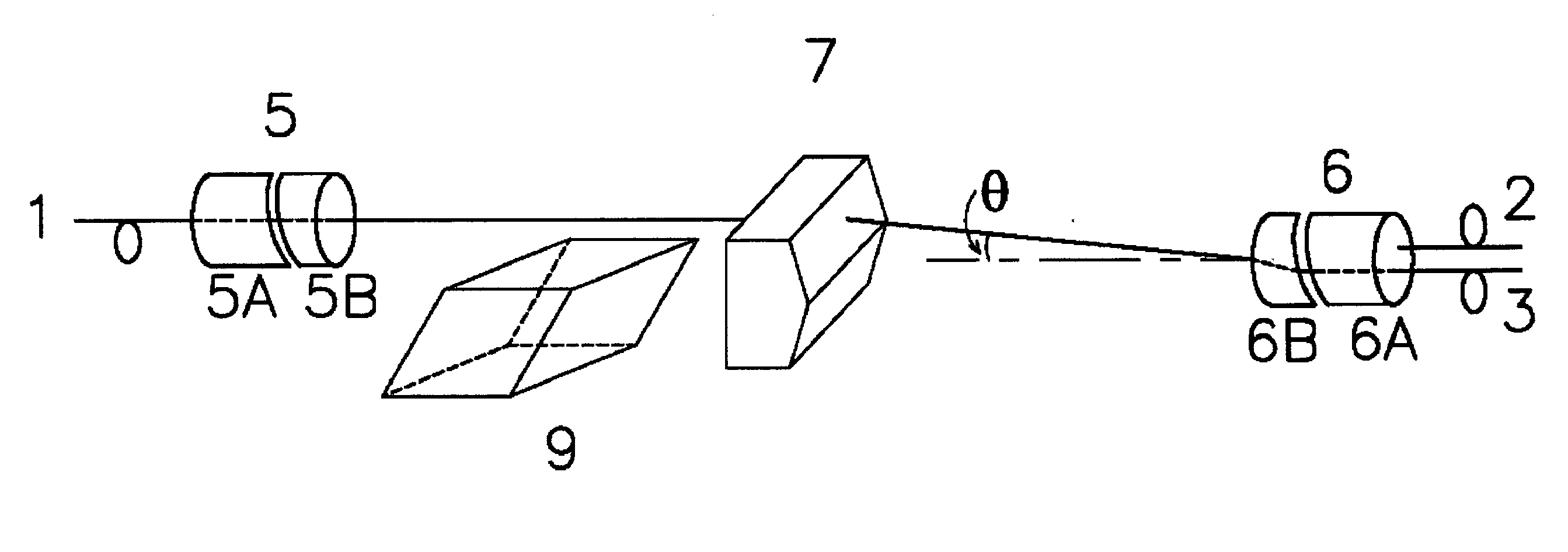
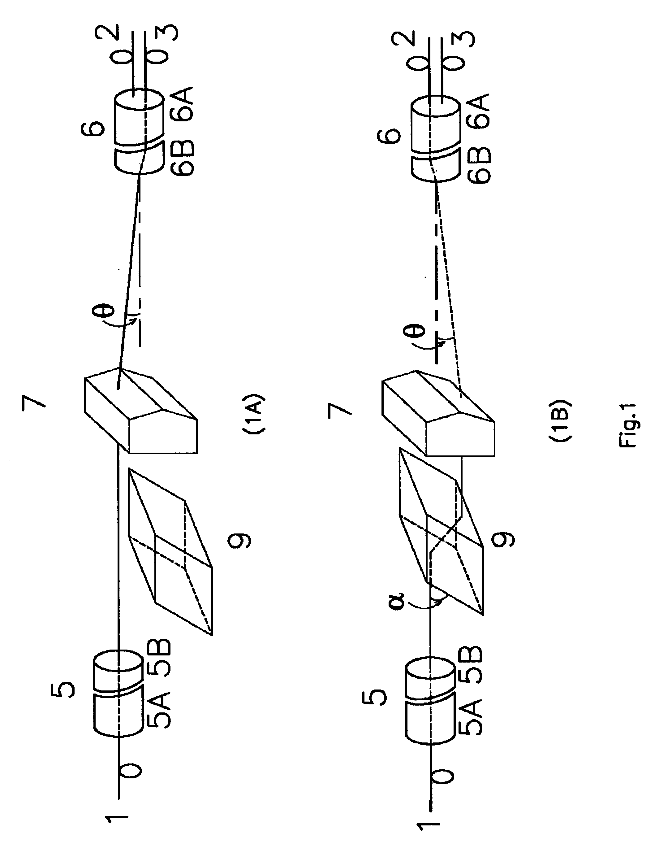
[0018] To more particularly illustrate the method and system in accordance with the present invention, refer now to FIG. 1, depicting a one-by-two fiber optic switch 100 incorporating aspects of the invention. FIG. 1A depicts a light path from 1 to 3 and FIG. 1B depicts a light path from 1 to 2. The invention relates to an optical switch comprising several optical components which are optically coupled along the longitudinal axis: a first fiber collimator 5 that expands and collimates light beam from fiber 1; an movable beam shifter 9 for switching light path between 1 to 3 and 1 to 2; a beam angle deflector 7 which deflects all beams with a correction angle, such that both optical path are propagating parallel; a dual fiber collimator that collimates two beam with one shared imaging lens. The switch described here is a simple opto-mechanical device in which the light beam goes to one fiber without beam shift element 9 in the path and goes into another fiber when the beam shift elem...

second embodiment

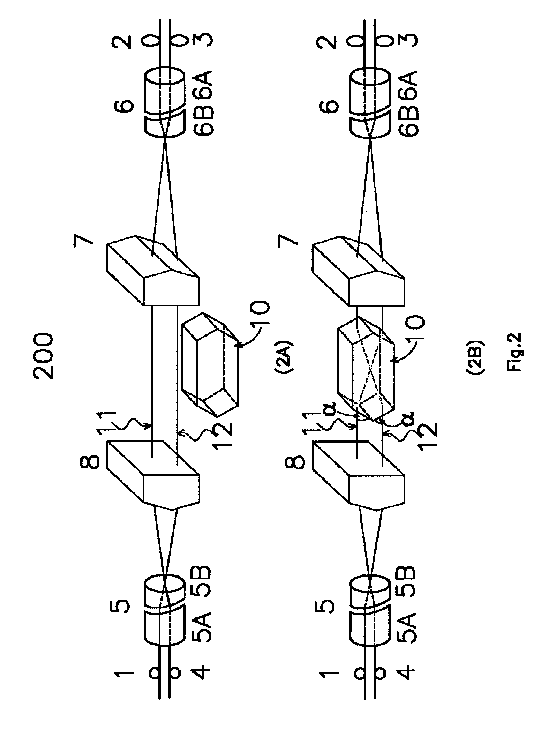
[0028] Referring to the FIG. 2, there is shown a two-by-two fiber optic switch 200 incorporating aspects of the invention. Switch 200 utilizes the optical elements described above and the same reference numerals are used to refer to the same parts. The switch 200 has four optical fiber ports, a first fiber 1 and a fourth fiber 4 input light beams through a dual collimator 5 and a second fiber 2 and a third output fiber 3 receive the light beams through a dual collimator 6 that is placed opposite to collimator 5. The two light beams from the dual collimator have an angle with respect to each other or two light beams need an entry angle in order to optimally couple into the dual collimator. In the inventive design, a light-bending device 7 and 8 are incorporated to correct the angle separations for collimator 5 and collimator 6, respectively. Therefore, light beam propagations between device 7 and device 8 become parallel.

[0029] As is apparent from the FIG. 2A, the switch is aligned s...

third embodiment

[0031] Referring to the FIG. 3, there is shown a mechanical wavelength add / drop fiber optic switch 300 incorporating aspects of the invention. Switch 300 utilizes the optical elements described above and the same reference numerals are used to refer to the same parts. The switch 300 has four optical fibers, a first fiber 1 and a fourth fiber 4 couple light beam through a dual collimator 5 and a second fiber 2 and a third fiber 3 couple light beam through a dual collimator 6 that is placed opposite to collimator 5. The two light beams from the dual collimator have an angle with respect to each other or two light beams need a separation angel in order to optimally couple into the dual collimator. In the inventive design, a light-bending device 7 and 8 are incorporated to correct the angle separations for collimator 5 and collimator 6, respectively. Therefore, light beam propagations become parallel between device 7 and device 8.

[0032] As shown in FIG. 3, an input beam 30 from fiber 1 ...


PUM


Abstract

The present invention provides improved optical switches in which only a spatial beam shifting of a small free space offset is required to direct optical pathways between plural fiber ports. This is achieved by spacing two fibers closely and collimating their beams with one imaging lens for compactness. Advantageously, the inventive switches incorporate beam correcting devices to render the beam propagations parallel, allowing light beams to be efficiently coupled into two fibers that sharing a single lens with substantially improved stability.

Description

[0001] The present invention is related to optical devices; more particularly, the invention relates to mechanical optical switches.BACKGROUND OF INVENTION[0002] Optic switch is a device for directing optical signals along selected fibers of an optic network, in which light signals are transmitted along optical fibers to transfer information from one location to another. The desirable optical switch performance include: high speed switching, low optical insertion loss, good repeatability, long operation lifetime, small size, and low cost. Optical switch is a key component in today's optic network, analogous to the electrical switches in electrical networks. However, it has not been widely adopted because its lack of reliability and its high cost associated with its fabrication difficulty.[0003] Mechanical fiber optic switches using movable light guiding elements for alternating optical beam paths to effectuate switching are the dominant optical switching component used in current te...

Claims


Application Information

Patent Timeline
Patent Type & Authority Applications(United States)
IPC IPC(8): G02B6/32G02B6/35
CPCG02B6/32G02B6/3524G02B6/356G02B6/3546G02B6/355G02B6/3528
Inventor ZHAO, JINGSHU, YONGJUN
Owner AGILTRON
Why Eureka
Try Eureka