
Device and method for controlling the beginning of a tool operation in fish treatment machine

a technology for treating machines and tools, applied in fish arranging, fish filleting, butchering, etc., can solve problems such as damage to scales, difficulty in arranging, and end product no longer meeting the demands of premium quality requirements

Inactive Publication Date: 2004-01-22
NORDISCHER MASCHINENBAU RUD BAADER GMBH CO KG
View PDF15 Cites 4 Cited by
  • Summary
  • Abstract
  • Description
  • Claims
  • Application Information

AI Technical Summary

Benefits of technology

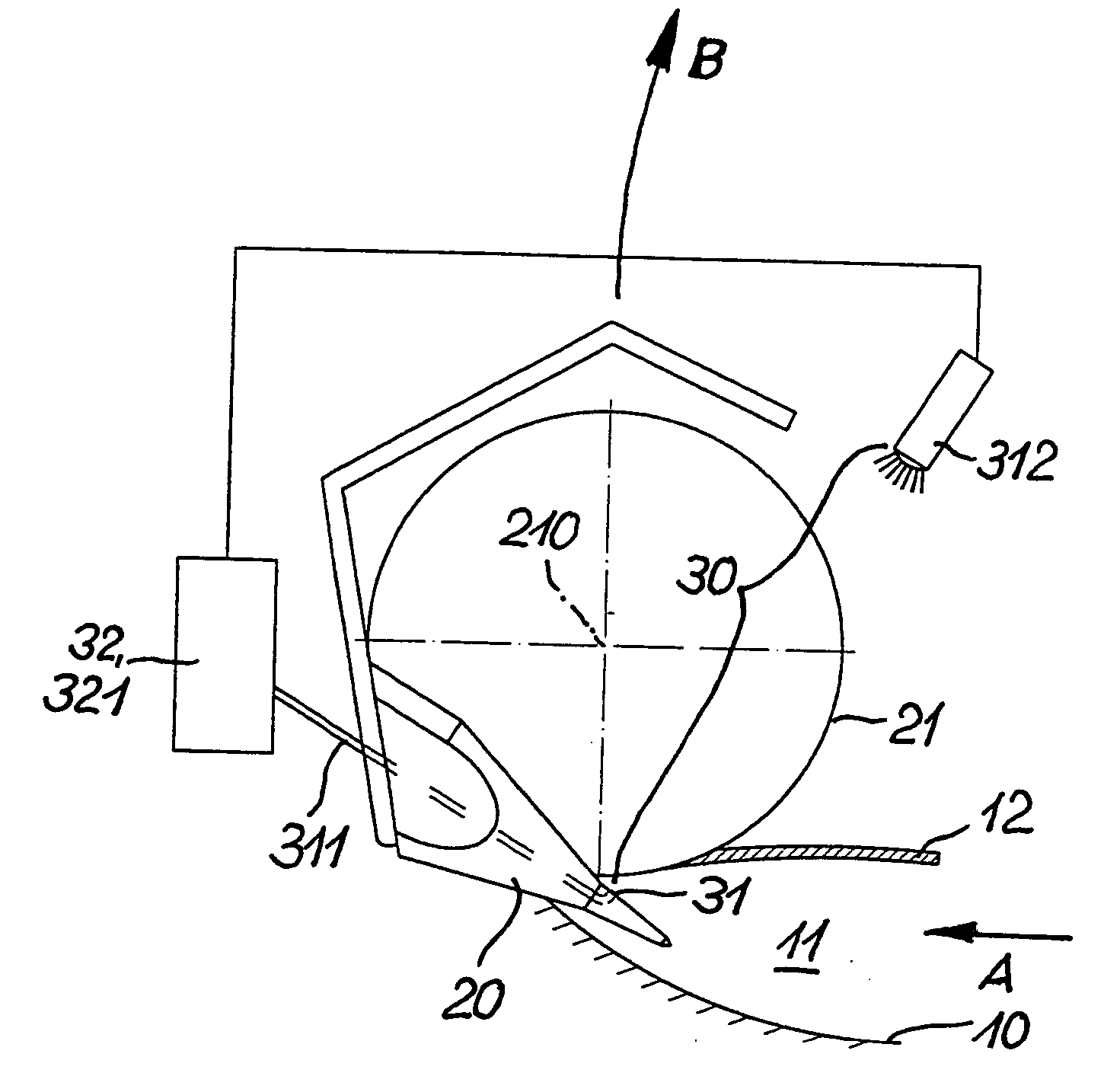
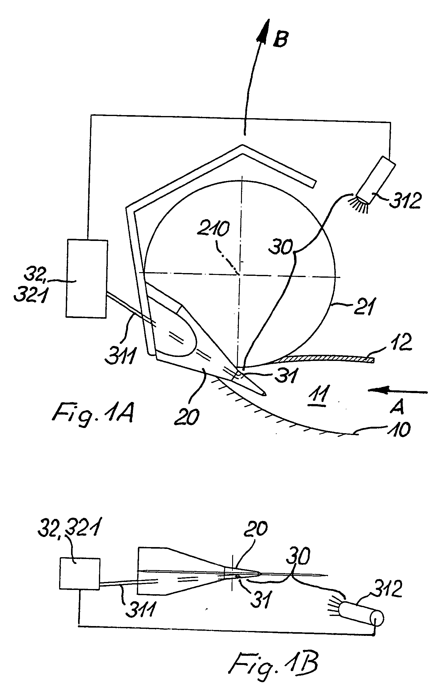
[0009] According to a preferred embodiment of the invention, the sensor may be a transmitter / receiver device in particular for electromagnetic waves, wherein monitoring of the fish / guide element position is advantageously effected optically. In this case a light source can be selected as the sensor, while the receiver can appropriately be arranged in the guide element itself and connected to the evaluating unit by optical fibres. In this case, advantageously, modulated light is used to exclude disturbing influences of extraneous light (daylight, lamps, etc.) as far as possible. In this embodiment, the receiver registers the modulated light emanating from the transmitter located outside the fish and preferably above it. If the point of the spike is located in the fish, then the receiver does not register a light signal, and the evaluating unit ascertains matching between actual and nominal values in order to initiate the actuating signal, whereupon the subsequent tools can penetrate into the abdominal cavity and work in or on the fish. If on the other hand the spike point misses the point of penetration, that is, the anus, and if it moves outside the abdominal cavity, then the light emitted by the transmitter is registered by the receiver at the spike point. This circumstance triggers a non-matching signal in the evaluating unit, causing the subsequent tools to remain in their rest position. The fish whose flank remains undamaged can be removed at the end of the conveying path of the transport device and introduced into the system anew.

Problems solved by technology

With the known procedures, due to the fact that the fish is guided only relatively loosely in the holding V-blocks of the chain conveyor or between conveyor belts and for example fish deformation cannot be compensated, difficulties arise if the anus or other region of penetration is missed by such a spike.
As a result of this, the spike pushes the fish sideways and then the point of the spike damages the scales covering the fish in the flank region.
However, in particular subsequent tools such as suction devices, scrapers and above all even the slitting knife which here operates in a functional unit with the spike but can also be used separately, which tools are shown e.g. in DE 198 29 376 A1, destroy the fish at unwanted locations, thus especially the top side of the fish, so that the end product no longer meets the demanded premium quality requirements.
This is a drawback particularly if, as described there, the aim is to make the so-called "princess cut", which up to now could be made manually only, by machine (to which cut a gutting method refers which ensures a work result which meets the highest quality requirements and leaves the last 2 to 3 cm of the ventral wall in the gill region closed), and if it is wished above all to make noble or high-value fish accessible to machine processing as well.
This circumstance triggers a non-matching signal in the evaluating unit, causing the subsequent tools to remain in their rest position.
This results in registration of a deviation between actual and nominal values with the consequences already described for non-actuation of the tools.

Method used


Image

  • Device and method for controlling the beginning of a tool operation in fish treatment machine
  • Device and method for controlling the beginning of a tool operation in fish treatment machine
  • Device and method for controlling the beginning of a tool operation in fish treatment machine

Examples


embodiment

OF EMBODIMENT

[0017] In FIGS. 1A and B can be seen a first embodiment of a spike assembly as used for example in a fish gutting machine of the kind shown in DE 198 29 376 A1. A fish 10 held with its ventral side facing upwards in a conveyor not shown in more detail here is conveyed tail first in the direction of arrow A. The abdominal cavity 11 and ventral wall 12 of the fish are here shown purely schematically. For the purpose of aligning the fish 10, a guide element designed as a spike 20 is arranged for penetration into the abdominal cavity through the anus opening, not described in more detail. This spike 20 comprises in the extent of its width a recess in which rotates a slitting blade 21 for slitting open the abdominal cavity. This slitting blade 21 slits open the fish, which is kept aligned by the spike 20, in its ventral wall 12 along the ventral seam as it advances in the direction of the arrow A, so that subsequently tools for extracting the entrails and cleaning the abdomi...


PUM


Abstract

In a device and method for controlling the commencement of operation of at least one tool in a fish processing machine, a guide element penetrates the interior of the fish so as to perform alignment of the fish before the tool begins its application. A monitoring device associated with the guide element includes a sensor for determining the guide element / fish position. An evaluating unit connected to the sensor compares nominal and actual position values. On reaching an adjustable nominal position value, a signal for actuating the tool is triggered. Therefore, the tool comes into operation only when the monitoring device yields an actual value for the fish position which corresponds to the nominal value when the guide element has penetrated properly.

Description

[0001] The invention concerns a device and a method for controlling the commencement of operation of at least one tool in a fish processing machine in which tool and fish are moved relative to each other along a given conveying path, wherein the position of the fish in relation to the tool is determined by means of a guide element which penetrates into the interior of the fish, and after alignment of the fish as a result of penetration of this guide element the tool begins its application to or intervention in the fish.STATE OF THE ART[0002] In the processing or treatment of fish it is necessary in many cases, particularly when the fish is not yet gutted, that is, the abdominal cavity is not yet cleaned, to align it in the region thereof in order to open it by means of a slitting blade and then extract the entrails by means of a suction device and / or carry out cleaning in this region by means of scrapers, brushes or the like. In a traditional procedure such as is described e.g. in D...

Claims


Application Information

Patent Timeline
IPC IPC(8): A22C25/08A22C25/12A22C25/14
CPCA22C25/08A22C25/147A22C25/145
Inventor GROBEHOLZ, WERNER
Owner NORDISCHER MASCHINENBAU RUD BAADER GMBH CO KG
Learn More