Method and apparatus for the actuation of the cantilever of a probe-based instrument

a technology of probe-based instruments and cantilevers, which is applied in the direction of instruments, mechanical roughness/irregularity measurements, and reradiation, etc., can solve the problems of inefficiency, limitation of the range of applications of this common type of piezo-electrically-driven probe, and insufficient gain of typical piezo-electric drives to excite the cantilever

Inactive Publication Date: 2004-02-05
GEORGIA TECH RES CORP
View PDF2 Cites 57 Cited by
  • Summary
  • Abstract
  • Description
  • Claims
  • Application Information

AI Technical Summary

Problems solved by technology

One potentially problematic characteristic of AFMs and other probe-based instruments lies in the technique employed to provide an external force to deflect or oscillate the instrument's cantilever.
This inefficiency limits the range of applications for this common type of piezo-electrically-driven probe.
As a result, the typical piezoelectric drive does not have enough gain to excite the cantilever sufficiently to produce a resonance peak that is easily located and differentiated from parasitic resonances.
A magnetic drive system has inherent limitations that considerably restrict its range of applications.
For instance, it requires a special magnetically coated cantilever and, accordingly, cannot be used in applications in which the cantilever is not capable of being coated with a magnetic material.
It also is not usable in applications in which magnetic properties of the sample and / or the environment cause unwanted deflection of the cantilever and introduce errors into the measurements.
The practical operating ranges of the magnetic drive system are also limited.
Even at this coil current, the heat load generated can cause thermal drift errors in the measurement of the AFM.
The frequency range of the magnetic drive system is also limited by the inductance of the drive coil.
Higher actuation forces can be achieved by using more loops in the drive coil, but this also increases the inductance and limits the maximum operating frequency.
Acoustic drive has distinct disadvantages that limit its effectiveness.
These resonances can be difficult to distinguish from the cantilever resonance.
The acoustic drive also has sufficient actuation force at a limited selection of operation frequencies and it can be a challenge to match the cantilever resonance with the operation frequency of the acoustic actuator.
If a user selects a resonance that does not overlap with the cantilever resonance, the measurements may be unstable.
In addition, while UFMs have been in use for almost a decade, no one has adapted an ultrasonic device as a general purpose cantilever actuator capable of deflecting the cantilever at a wide range of frequencies.
Such an energy transfer mechanism requires constant contact of the tip with sample surfaces, and would not work in the case of TappingMode AFM where the tip is in contact with surfaces only 1 to a few percent of time.
However, when the cantilever is driven acoustically by a piezoelectric drive, fluid damping and other effects reduce that response to the point that the cantilever resonance peak cannot be differentiated from parasitic resonance peaks.
The high attenuation of ultrasonic waves in air may limit the frequency of operation.

Method used


Image

  • Method and apparatus for the actuation of the cantilever of a probe-based instrument
  • Method and apparatus for the actuation of the cantilever of a probe-based instrument
  • Method and apparatus for the actuation of the cantilever of a probe-based instrument

Examples


Embodiment Construction

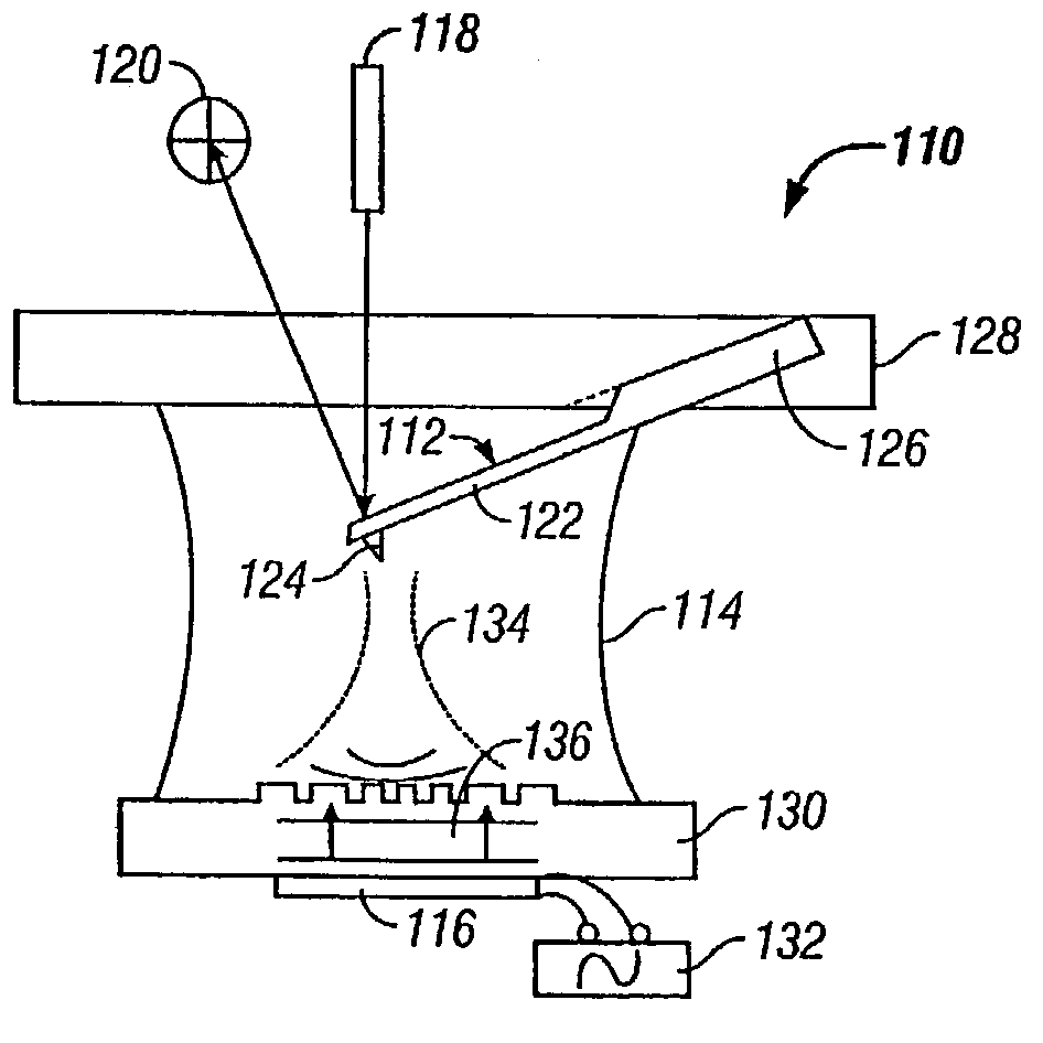
[0087] An ultrasonic actuator of the type described above can be used to drive an AFM cantilever to oscillate at virtually any desired frequency significantly below the RF carrier frequency. An ultrasonic actuator therefore can be directly used as TappingMode actuator in an AFM. A TappingMode AFM 210 using an ultrasonic actuator is shown schematically in FIG. 8. As with the more theoretical embodiment of FIG. 3B, the instrument 210 includes a conventional probe 212, an ultrasonic actuator 216, and a detector 220. The probe 212 is configured to operate in a fluid cell 214 containing a sample S. It includes a cantilever 222 having a base affixed to a support 226 and a free end bearing a tip 224. Also as in the embodiment of FIG. 3B, an ultrasonically transmissive substrate 230 is placed below the cantilever 222. A focusing device such as a Fresnel lens (not shown) may, if desired, be placed on or in the substrate 230. The ultrasonic actuator 216 is mounted on the bottom of the substra...


PUM

PropertyMeasurementUnit
frequencyaaaaaaaaaa
frequencyaaaaaaaaaa
frequencyaaaaaaaaaa

Abstract

An electromagnetic drive causes a cantilever of a probe-based instrument to deform flexurally by transmitting a high frequency AC signal through an electromagnetic actuator located in the vicinity of the cantilever. The AC signal preferably is an RF carrier signal having a frequency that is substantially higher than the resonant frequency of the cantilever. The carrier signal may, if desired, be modulated with a lower frequency modulation signal to induce the cantilever to oscillate, preferably at resonance. Alternatively, the carrier signal may be transmitted to the electromagnetic actuator without being modulated in order to deflect the cantilever quasi-statically. Cantilever response can then be monitored either directly in response to the imposition of the electromagnetically induced deformation of the cantilever in response to probe / sample interaction to obtain measurements regarding characteristics of the sample, the environment, and / or the cantilever.

Description

[0001] This is a continuation-in-part of U.S. patent application Ser. No. 10 / 095,850, entitled "Method and Apparatus for the Ultrasonic Actuation of the Cantilever of a Probe-Based Instrument," filed Mar. 12, 2002 which, in turn, claims priority under 35 USC .sctn.1.119(e) on prior U.S. Provisional Patent Application Serial No. 60 / 313,911, filed Aug. 21, 2001. The subject matter of both applications is hereby incorporated by reference in their entirety.[0002] 1. Field of the Invention[0003] The present invention is directed to probe-based instruments and, more particularly, relates to a method and apparatus for driving a cantilever of such an instrument using either acoustic radiation pressure generated by an ultrasonic actuator or an interaction generated by an electromagnetic drive.[0004] 2. Description of Related Art[0005] Several probe-based instruments monitor the interaction between a cantilever-based probe and a sample to obtain information concerning one or more characterist...

Claims


Application Information

Patent Timeline
Patent Type & Authority Applications(United States)
IPC IPC(8): G01N29/06G01N29/24G01N29/34G01Q30/14G01Q60/32G01S17/08
CPCB82Y35/00G01N29/0681G01N29/2456G01N29/346Y10S977/872G01N2291/0427G01Q30/14G01Q60/32G01S17/08G01N2291/02827
Inventor DEGERTEKIN, F. LEVENTSU, CHANMINNEILSON, PETER G.
Owner GEORGIA TECH RES CORP
Why Eureka
Try Eureka