Rotary machine with axial stop incorporating a current generator

a current generator and axial stop technology, applied in the direction of bearings, dynamo-electric machines, shafts, etc., can solve the problems of not always being able to remotely locate control cabinets in protected environments, unable to completely deactivate batteries, damage or destruction

Inactive Publication Date: 2004-02-05
SOCIETE DE MECHANIQUE MAGNETIQUE
View PDF6 Cites 40 Cited by
  • Summary
  • Abstract
  • Description
  • Claims
  • Application Information

AI Technical Summary

Benefits of technology

0011] The present invention seeks to remedy the above-mentioned drawbacks and to provide a rotary machine incorporating an emergency powe

Problems solved by technology

However, the rotary shaft is allowed to land on the auxiliary bearings only below a certain speed which is slow enough to avoid any risk of damaging or destroying the shafts and the bearings.
For reasons of cost and equipment mobility, it is not always possible for control cabinets to be located remotely in protected environments.
Since it is not possible to totally deactivate batteries, which is essential for equipment in explosive zones, the batteries must be located outside the dangerous environment.
Consequently, such a configuration for the system comprising the system and its power supplies does not

Method used


Image

  • Rotary machine with axial stop incorporating a current generator
  • Rotary machine with axial stop incorporating a current generator
  • Rotary machine with axial stop incorporating a current generator

Examples


Embodiment Construction

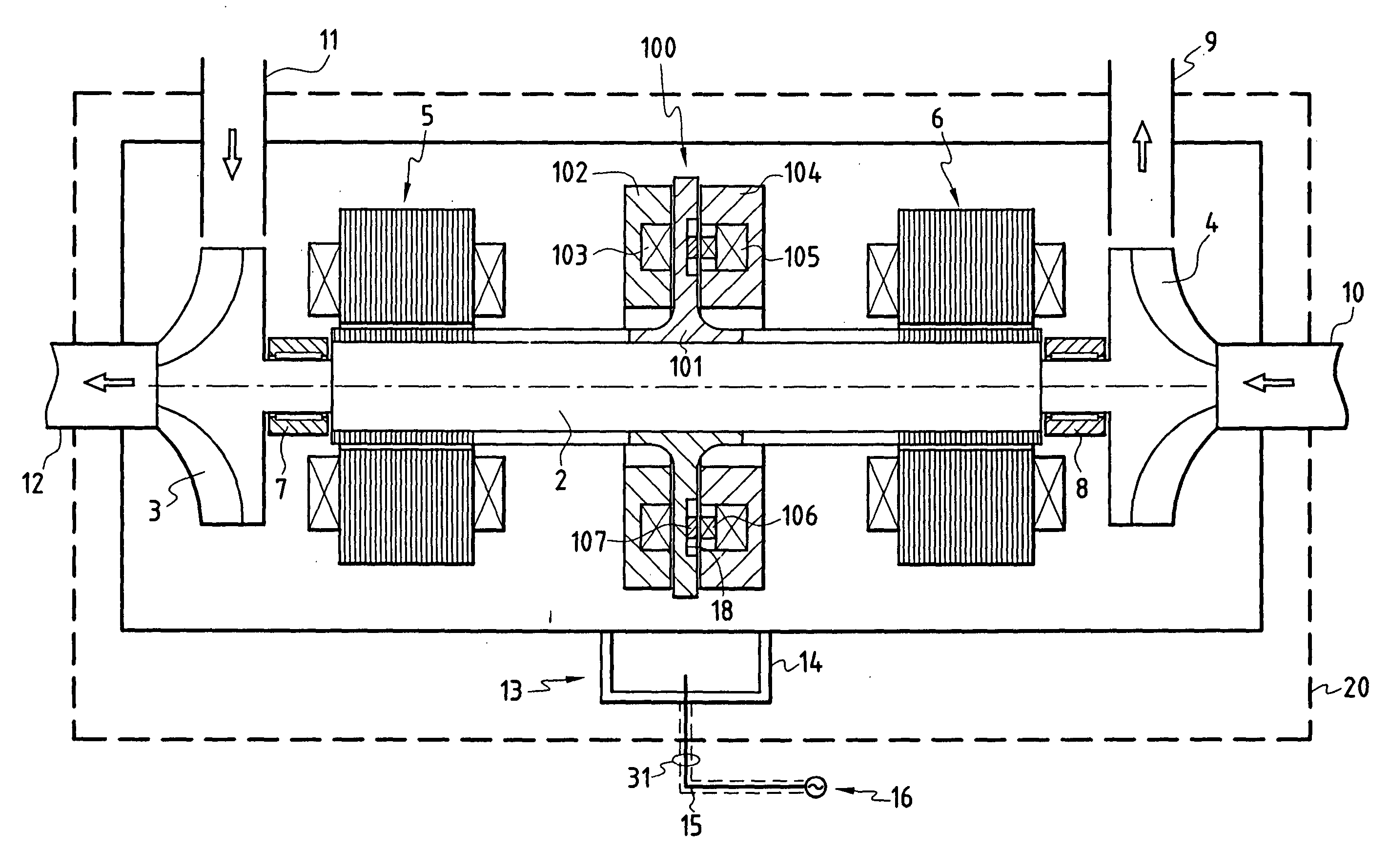
[0029] FIG. 1 shows a turboexpander for operating in an explosive atmosphere zone 20 and including an axial abutment device 100 fitted with electricity generator means in accordance with the invention. The compressor mainly comprises a rotary shaft 2 supported by first and second radial active magnetic bearings 6 and 7 which are electrically controlled by a control device 13 situated in the zone 20, and preferably incorporated in the structure of the compressor. The control device 13 may be placed either in a box 14 that is treated to be explosion-proof if the machine is to operate in an explosive atmosphere zone 20, or else in a conventional junction box for use in environments that do not require special precautions.

[0030] The control device 13 is powered mainly from an electricity power supply network 16 with a connection point situated outside the zone 20. The device 13 is connected to the network 16 by a conductor 15 which has a leakproof sheath 31 to isolate the conductor 15 f...


PUM


Abstract

The rotary machine comprises a rotary shaft (2) supported by first and second radial magnetic bearings (5, 6) that are electrically controlled by a control device (13), said rotary shaft being fitted with an axial abutment device (100) comprising a rotor formed by a disk (101) secured to the rotary shaft (2) and interposed between first and second stators (102, 104) formed annularly around the rotary shaft and each including at least one annular coil (103; 105) controlled electrically by a system for servo-controlling the axial position of the rotary shaft. The stator (104) of the axial abutment device (100) further comprises a secondary induction circuit (106), and the disk (101) secured to the rotary shaft comprises a primary induction circuit (107) so that during rotation of the shaft, electricity is excited in the secondary induction circuit in order to supply energy to the radial magnetic bearings.

Description

[0001] The present invention relates to a rotary machine, for example a turbopump, comprising a rotary shaft supported by radial active magnetic bearings. More particularly, the invention relates to an emergency supply of electricity to radial and axial magnetic bearings, in particular for devices that are designed to operate in explosive atmospheres.PRIOR ART[0002] The use of rotary machines having magnetic bearings is becoming more and more widespread. The active magnetic bearings used in machines of this type use electromagnet devices which are operated by electricity and therefore require an electrical power supply.[0003] FIG. 7 shows an example of a turboexpander. The machine comprises a rotary shaft 2 which is surrounded by two radial magnetic bearings 5 and 6 placed in the vicinity of the two ends of the shaft, together with a double-acting axial abutment. First and second wheels 3 and 4 are fixed to respective ends of the shaft 2. The first wheel 3 is situated on the left of...

Claims


Application Information

Patent Timeline
IPC IPC(8): F01D25/16F02C7/06F04D29/04F04D29/056F04D29/058F16C32/04F16C39/06H02K3/26H02K21/12H02K21/22
CPCF16C32/0442F16C32/0457F16C2360/44F16C32/0476F16C2360/42F16C32/0465F16C32/0489F16C41/004
Inventor BRUNET, MAURICESCHROEDER, ULRICHTREMAUDANT, YANN
Owner SOCIETE DE MECHANIQUE MAGNETIQUE
Why Eureka
Try Eureka