Electric brake apparatus

a technology of electric brakes and brake plates, which is applied in the direction of brake types, brake elements, actuators, etc., can solve the problems of poor mounting of electric brake plates

Inactive Publication Date: 2004-02-12
ADVICS CO LTD
View PDF3 Cites 7 Cited by
  • Summary
  • Abstract
  • Description
  • Claims
  • Application Information

AI Technical Summary

Benefits of technology

[0009] In the electric brake apparatus, the gear train which transmits the rotational drive force of the electric motor to the input member of the screw feed mechanism as a rotational drive force is disposed between the electric motor and the screw feed mechanism. Therefore, by suitably selecting the structure of the gear train, the layout of the electric motor with respect to the screw feed mechanism can be optimized. Accordingly, in this electric brake apparatus, the freedom of installation of the electric motor with respect to the screw feed mechanism can be increased, the axial dimension of the structure comprising the electric motor and the screw feed mechanism can be shortened, and the mountability of the electric brake apparatus can be improved.
[0010] In the present invention, preferably, the output shaft of the electric motor and the screw shaft of the screw feed mechanism are disposed side by side. In this case, the electric motor can be compactly arranged with respect to the screw feed mechanism, a decrease in the size of the electric brake apparatus can be achieved, and the mountability of the brake apparatus can be further improved.
[0011] In the present invention, preferably, an output gear of the gear train is integrally formed on the input member of the screw feed mechanism. In this case, the number of parts in the electric brake apparatus can be decreased, the size and weight of the electric brake apparatus can be decreased, and the cost of the apparatus can also be decreased.

Problems solved by technology

As a result, the mountability of the electric brake apparatus may be poor, particularly when the apparatus is mounted on a vehicle having limited mounting space.

Method used


Image

  • Electric brake apparatus
  • Electric brake apparatus
  • Electric brake apparatus

Examples


first embodiment

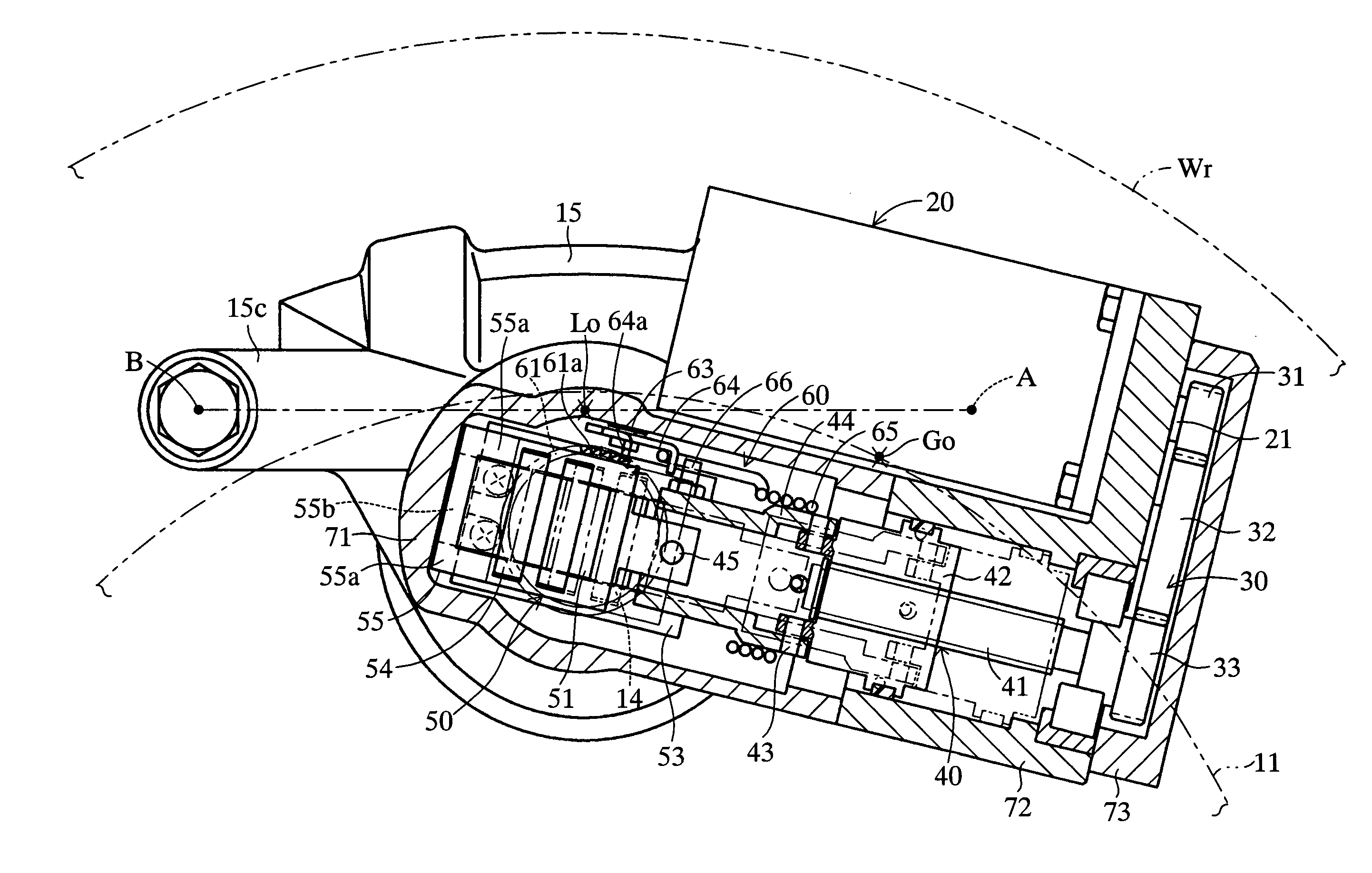
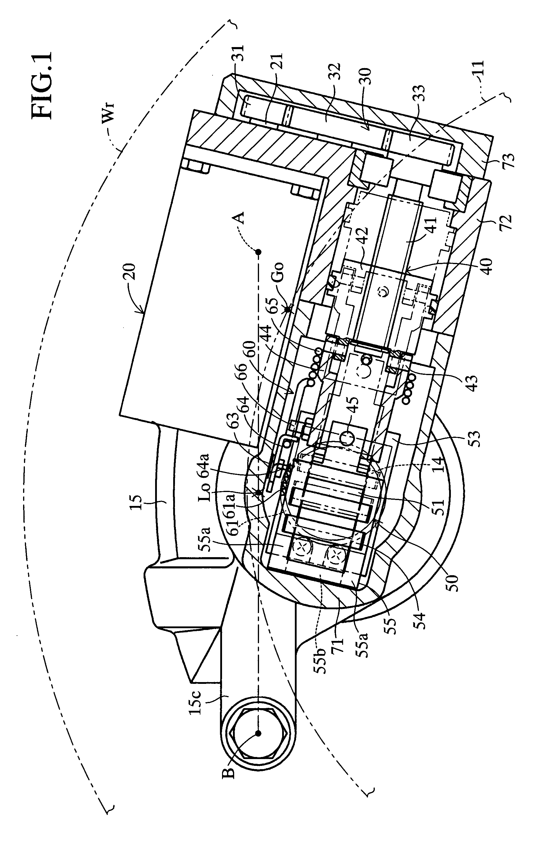
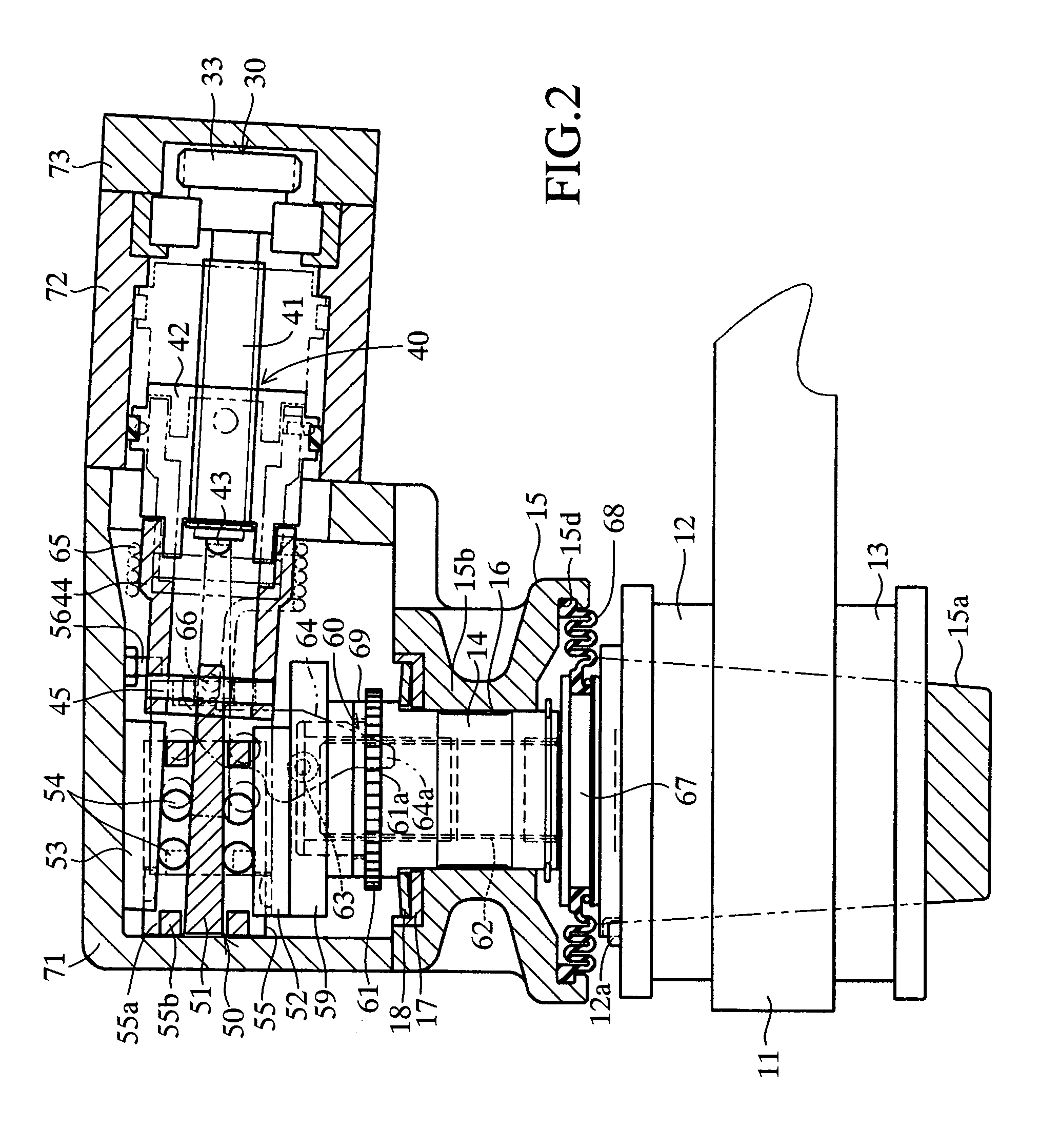
[0020] Below, preferred embodiments of the present invention will be described while referring to the accompanying drawings. FIG. 1 and FIG. 2 show the present invention being employed as an electric disc brake apparatus for a vehicle. The electric disc brake apparatus of the present embodiment includes an inner brake pad 12 and an outer brake pad 13 which can grasp between them a brake rotor 11 which is integral with a wheel (in FIG. 1, the location of the inner diameter of the wheel rim is shown by the imaginary line Wr), and a piston 14 and a caliper 15 which can move the brake pads 12 and 13 in the axial direction of the rotor 11 towards the braking surfaces of the brake rotor 11.

[0021] The illustrated electric disc brake apparatus includes an electric motor 20, a gear train 30, a screw feed mechanism 40, and a wedge transmission mechanism 50 for applying a pressing force in the axial direction of the rotor 11 to the piston 14 and the caliper 15. The electric disc brake apparatu...

fourth embodiment

[0046] FIGS. 5 and 6 show the present invention being employed as an electric disc brake apparatus for a vehicle. The disc brake apparatus of the present embodiment includes an inner brake pad 212 and an outer brake pad 213 which can grasp between them a brake rotor 211 which is integral with a wheel (in FIG. 5, the location of the inner diameter of the wheel rim is shown by the imaginary line Wr), and a piston 214 and a caliper 215 which can move the brake pads 212 and 213 in the axial direction of the rotor 211 towards the braking surfaces of the brake rotor 211.

[0047] The illustrated disc brake apparatus includes an electric motor 220, a gear train 230, a screw feed mechanism 240, and a wedge transmission mechanism 250 for applying a pressing force in the axial direction of the rotor 211 to the piston 214 and the caliper 215. The electric disc brake apparatus also includes an automatic gap adjusting mechanism 260 for automatically adjusting a gap between the brake pads 212 and 21...


PUM


Abstract

An electric brake apparatus includes an electric motor which generates a rotational drive force. A gear train is driven by the electric motor and generates a rotational drive force. A screw feed mechanism is driven by the gear train and converts the rotational drive force from the gear train into a linear drive force. A wedge transmission mechanism is driven by the screw feed mechanism and converts the linear drive force from the screw feed mechanism into a linear drive force transverse to the linear drive force from the screw feed mechanism. A piston is driven by the wedge transmission mechanism in an axial direction of the piston and generates a braking force.

Description

[0001] 1. Field of the Invention[0002] The present invention relates to an electric brake apparatus in which a braking force is generated by the rotational drive force of an electric motor.[0003] 2. Description of the Related Art[0004] In one known type of electric brake apparatus, the rotational drive force of the electric motor is converted by a screw feed mechanism into a drive force in the axial direction of a screw shaft of the screw feed mechanism, and the drive force in the axial direction of the screw shaft is converted by a wedge transmission mechanism into a drive force in the axial direction of a piston. The piston is driven by this drive force in its axial direction to generate a braking force. An example of such an electric brake apparatus is disclosed in Japanese Patent Application Laid-Open (kokai) No. 62-127533.[0005] In such an electric brake apparatus, the rotating output shaft of the electric motor and the screw shaft of the screw feed mechanism are disposed in se...

Claims


Application Information

Patent Timeline
Patent Type & Authority Applications(United States)
IPC IPC(8): F16D65/18F16D65/14
CPCF16D65/18F16D65/567F16D2121/24F16D2125/66F16D2125/48F16D2125/52F16D2125/40
Inventor MURAYAMA, TAKASHIOBA, DAIZO
Owner ADVICS CO LTD
Why Eureka
Try Eureka