Pressure support system and method and a pressure control valve for use in such a system and method

a technology of pressure support system and pressure control valve, which is applied in the direction of valves, operating means/releasing devices, respirators, etc., can solve the problems of less sophisticated cpap devices, and add significant cost, size and weight to the pressure support system

Inactive Publication Date: 2004-02-26
RIC INVESTMENTS LLC
View PDF37 Cites 99 Cited by
  • Summary
  • Abstract
  • Description
  • Claims
  • Application Information

AI Technical Summary

Benefits of technology

[0007] Conventional pressure support devices with this configuration attempt to minimize noise due to exhausting of gas through the pressure control valve assembly to atmosphere by providing a dedicated muffler in the exhaust path. However, such a muffler is disadvantageous in that it adds significant cost, size, and weight to the pressure support system.

Problems solved by technology

However, such a muffler is disadvantageous in that it adds significant cost, size, and weight to the pressure support system.
In addition, it is known to have the less sophisticated CPAP devices monitor the pressure or flow of breathing gas delivered to the patient and adjust the pressure or flow in a feedback fashion to meet the desired prescription pressure level.
However, as noted above, the present inventors appreciated that such a muffler is undesirable in that it adds significant cost, size, and weight to the pressure support system.
However, this pressure control technique is disadvantageous in that it requires two valve elements, which increases the cost and size of the pressure support system.
In addition, because the pressure in the patient circuit affects the position of the piston, it is relatively difficult to control the position of the piston, and, hence the pressure in the patient circuit, with a high degree of accurately with a minimal amount of energy.
A disadvantage with a pressure support system that uses motor speed to control the pressure or flow of the gas delivered to the patient is that it is difficult to rapidly transition from one pressure level to another.
Because of the relatively high rotational velocity or the relatively large mass of the blower, i.e., impeller, it is difficult to increase or decrease the motor speed by the required amount in the necessary short time period to achieve these pressure variations.
If the blower speed is not reduced fast enough during the transition from the inspiratory to the expiratory phase of the breathing cycle, for example, the patient begins exhaling against a pressure head, which is generally not conducive to patient comport.
Changing the motor speed to control the pressure or flow delivered to the patient also subjects the pressure generator, specifically the blower, to relatively large mechanical and electrical stresses, which increase the wear on the blower.
Increased wear may reduce the blower's operating life or require that the blower be manufactured to withstand such stresses, which increases the overall cost of the blower.

Method used


Image

  • Pressure support system and method and a pressure control valve for use in such a system and method
  • Pressure support system and method and a pressure control valve for use in such a system and method
  • Pressure support system and method and a pressure control valve for use in such a system and method

Examples


Embodiment Construction

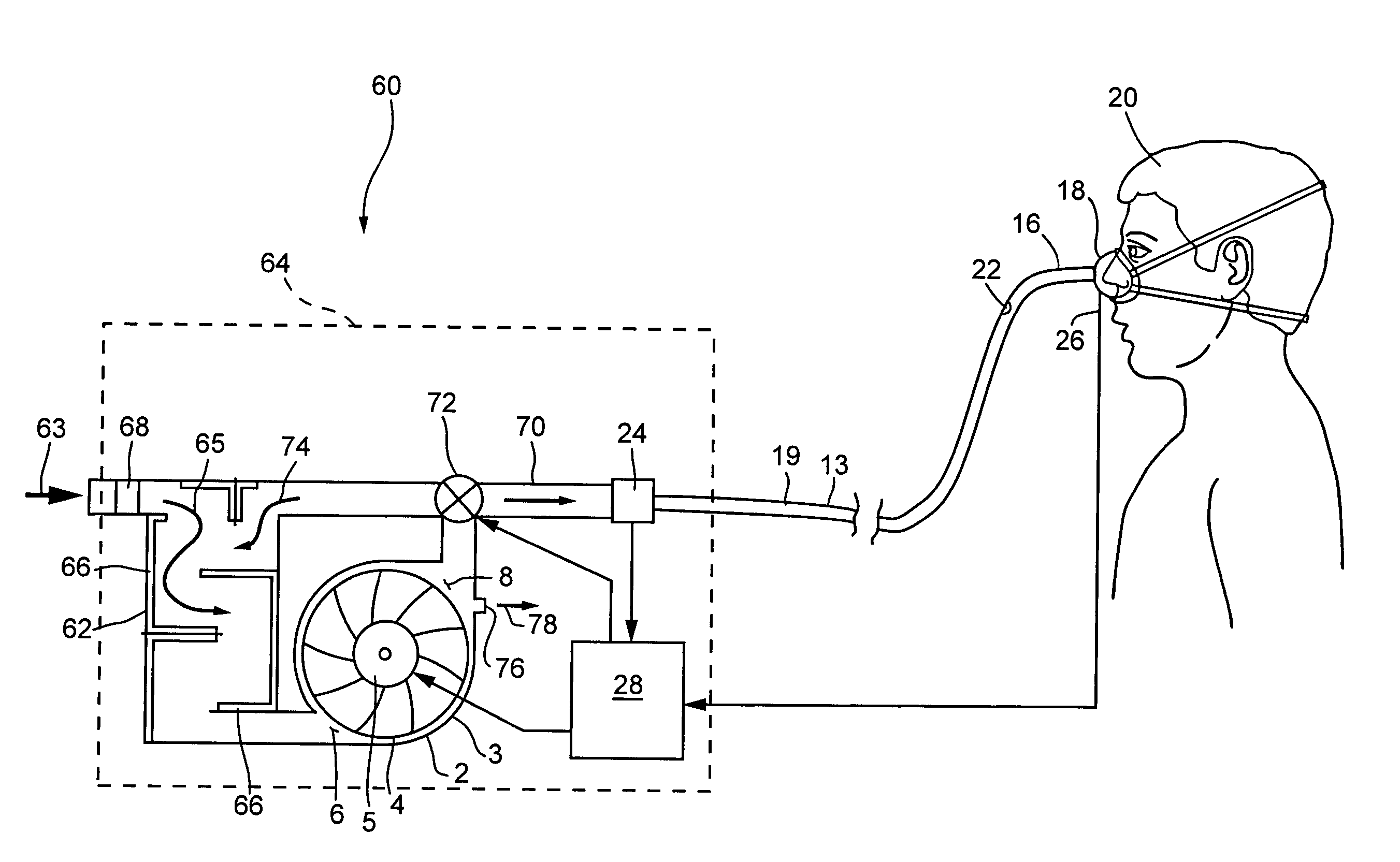
[0038] A pressure support system according to the principles of the present invention will now be described with reference to FIG. 4. For simplicity of description, like elements in the description of the present invention shown in FIG. 4 and in the description of the conventional pressure support systems shown in FIG. 1 have like reference numbers.

[0039] Pressure support system 60 includes a pressure generator in the form of a blower assembly 2 having a blower housing 3, a fan 4 contained within the blower housing, a motor 5 for driving fan 4, an inlet potion or intake 6, and an outlet portion 8. Inlet 6 is coupled to a first conduit 62 that communicates the inlet of the blower assembly to a source of gas 63 for the pressure generator, such as ambient atmosphere. It is to be understood that other sources of gas can be used instead of, or in addition to, the air from the ambient atmosphere. For example, a supply of oxygen or an oxygen mixture can be provided as source of breathing g...


PUM


Abstract

A pressure support system having enhanced noise reduction and a valve assembly for use in pressure support system. The pressure support system includes a pressure generator having an inlet and an outlet. A first conduit defining a tortuous path is coupled between a gas source and the inlet of the pressure generator. A second conduit coupled to the outlet of the pressure generator delivers the flow of gas from the pressure generator to a patient. A valve assembly communicates gas from the second conduit to the first conduit to control the pressure or a rate of the flow of gas in the second conduit. By communicating gas from the second conduit to the first conduit, the noise associated with exhausting gas from the second conduit is muffled by the tortuous path of the first conduit.

Description

[0001] 1. Field of the Invention[0002] The present invention pertains to a pressure support system and a method of providing pressure support to a patient, and, more particularly, to a pressure support system and method having enhanced noise reduction, as well as a pressure control valve assembly for use in a pressure support system.[0003] 2. Description of the Related Art[0004] Pressure support systems that provide a flow of gas to an airway of a patient at an elevated pressure via a patient circuit to treat a medical disorder are well known. For example, it is known to use a continuous positive airway pressure (CPAP) device to supply a constant positive pressure to the airway of a patient to treat obstructive sleep apnea (OSA). It is also known to provide a positive pressure therapy in which the pressure of gas delivered to the patient varies with the patient's breathing cycle or varies with the patient's effort to increase the comfort to the patient. It is further known to provid...

Claims


Application Information

Patent Timeline
Patent Type & Authority Applications(United States)
IPC IPC(8): A61M16/00A61M16/08A61M16/20
CPCA61M16/08A61M2205/42A61M16/202A61M16/0069Y10S251/905A61M16/0866A61M16/107Y10T137/7785Y10T137/86622
Inventor TRUITT, PATRICK W.LORDO, RICHARD J.GESNER, JOSEPH J.
Owner RIC INVESTMENTS LLC
Why Eureka
Try Eureka