Mobile elevator working and load-lifting platform

a technology for lifting platforms and elevators, applied in the direction of lifting devices, building scaffolds, structural elements, etc., can solve the problems of less stable vehicles, and achieve the effect of improving the manoeuvrability of elevating platforms

Inactive Publication Date: 2004-02-26
JULIEN ROMAIN
View PDF0 Cites 32 Cited by
  • Summary
  • Abstract
  • Description
  • Claims
  • Application Information

AI Technical Summary

Benefits of technology

0005] The object of the invention is thus to improve upon manoeuvrability of elevatable platforms suppo

Problems solved by technology

The problem with such vehicles is to reconcile manoeuvrability with stability.
With a higher center of gravity,

Method used


Image

  • Mobile elevator working and load-lifting platform
  • Mobile elevator working and load-lifting platform
  • Mobile elevator working and load-lifting platform

Examples


Embodiment Construction

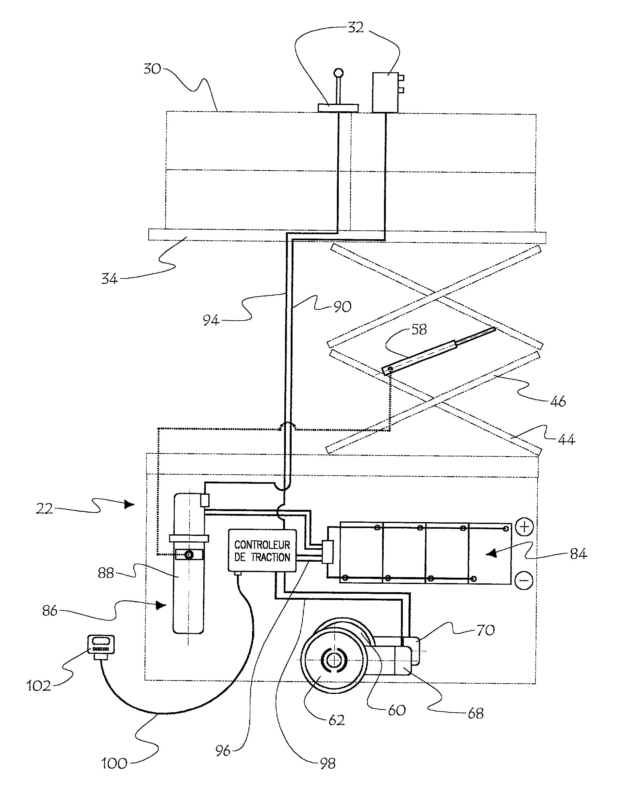
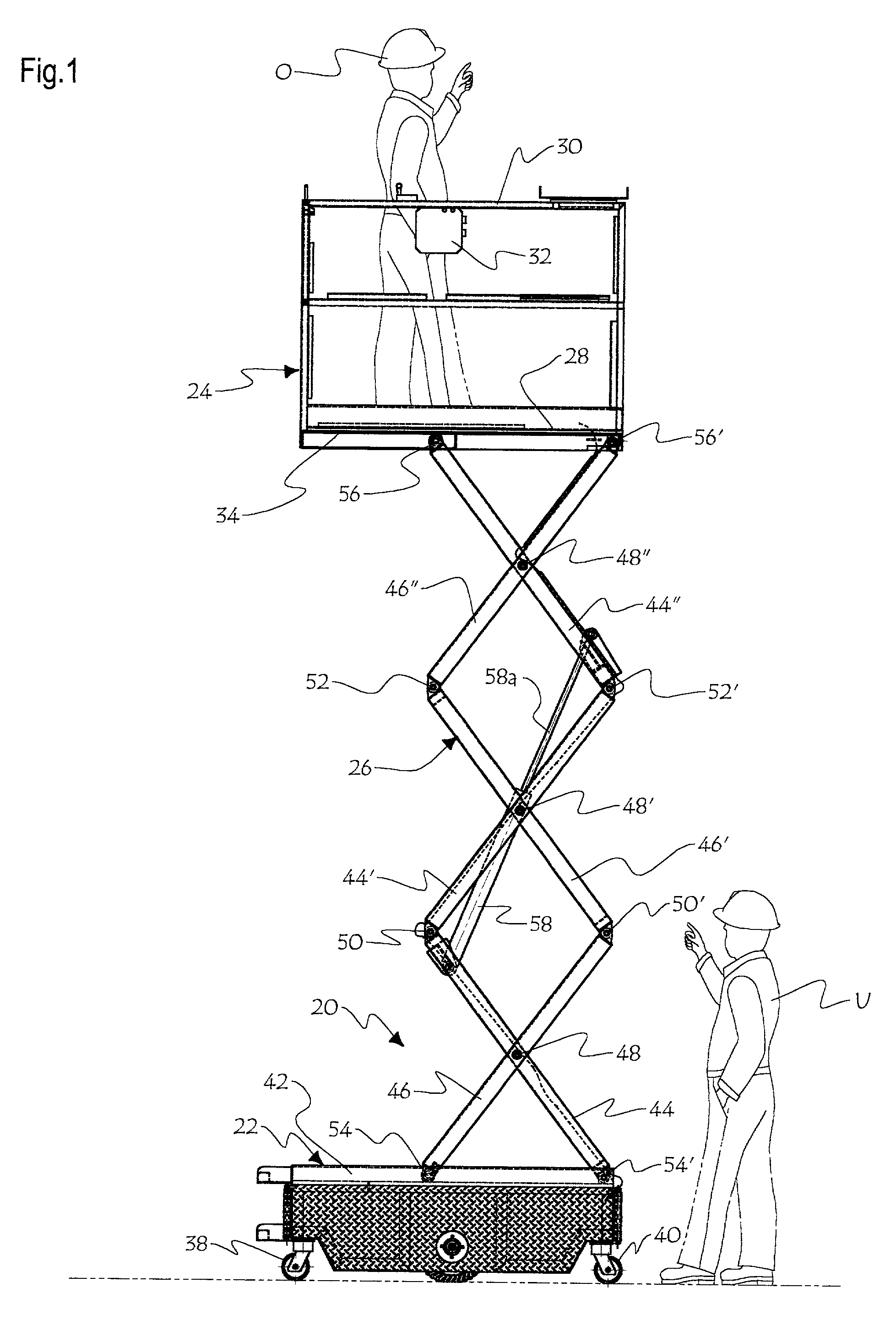
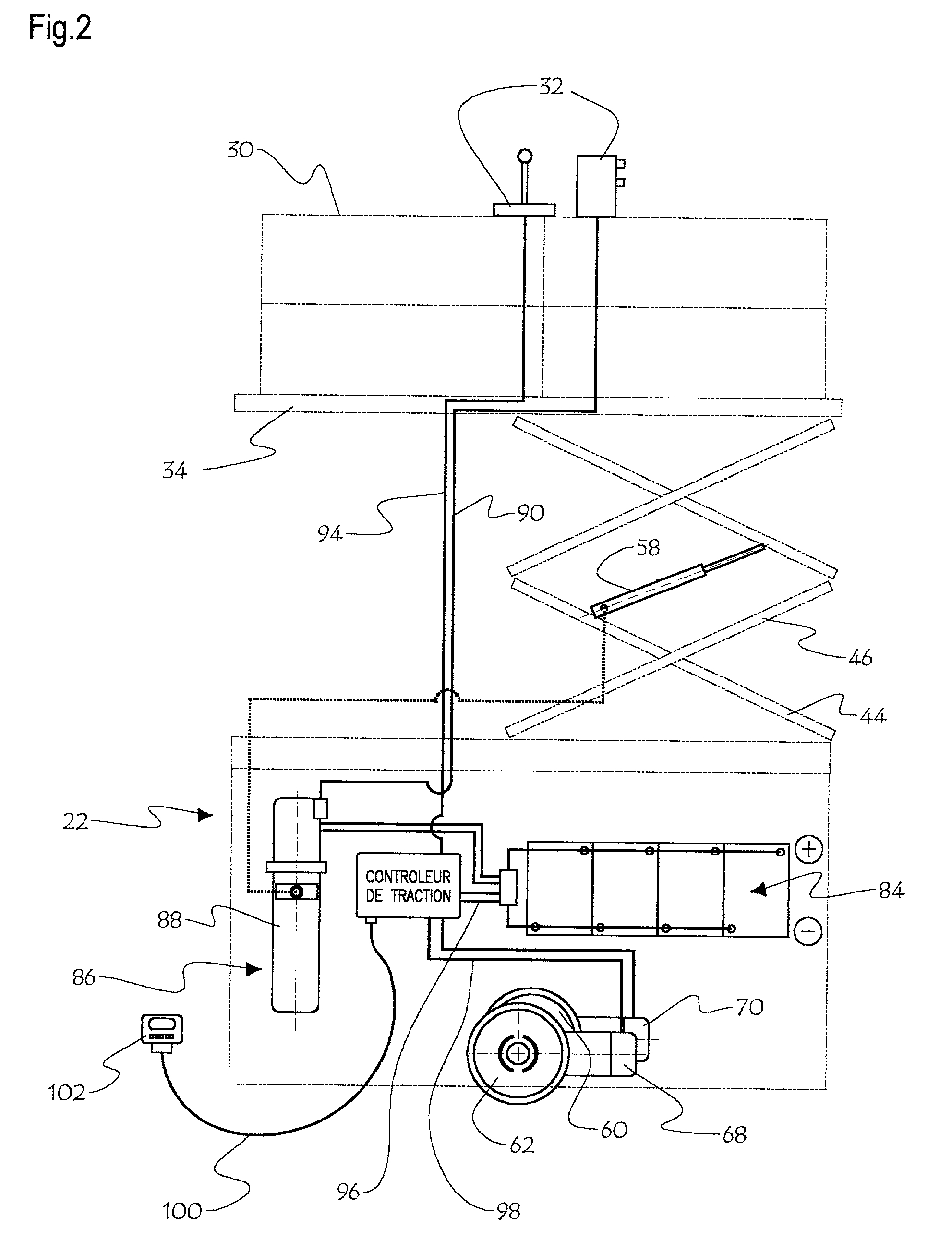
[0023] Elevating platform vehicle 20 illustrated in FIG. 1 generally consists of a ground carriage 22 at the bottom end, a platform 24 at the top end, and a scissor linkage assembly 26 interconnecting the carriage 22 and the platform 24.

[0024] Platform 24 defines a bottom platform bed 28, which supports upright guard ramp members 30. A remote-control vehicle control unit 32, detailed later, is mounted to an upper section of guard ramps 30, at arm's length for an operator 0 standing on the platform bed 28. A rail member 34 is provided against the underface of platform bed 28.

[0025] Ground carriage 22, shown in FIG. 3, generally consists of a box-like rigid frame 36, defining a front end 36a, a rear end 36b, and a middle portion 36c located intermediate the front end 36a and the rear end 36b. At each of the two opposite lateral sides of the front end 36a of carriage 22, is provided a swivel caster 38, 38; and at each of the two opposite lateral sides of the rear end 36b of carriage 22...


PUM


Abstract

A ground-movable load-lifting vehicle for lifting a load over ground. The vehicle comprises a platform bed, a ground-movable carriage, and an extendible scissor linkage assembly supporting the platform bed spacedly over the carriage. A hydraulic ram system enables power extension of the scissor linkage assembly against the bias of a load supported by said platform bed. The carriage further includes peripheral ground-engageable pivotal casters, rotatably mounted to the carriage in spaced apart fashion, and a pair of ground-engageable drive wheel assemblies, mounted for relative movement to a central portion of the carriage, wherein the drive wheel assemblies provide omnidirectional displacement capability for this load-lifting vehicle. A power unit, controlled by an electronic circuit, powers both the hydraulic rams of the scissor linkage assembly and the drive wheel assemblies.

Description

[0001] This invention relates to elevatable platforms supported by a ground movable carriage.[0002] It is known to provide movable and elevatable scaffold assemblies or lifts, for workmen in view of making installations of for example electrical wiring, heating ducts or the like in ceiling structures. Such movable / elevatable scaffold assemblies typically include a wheeled motorized base, a scissor linkage assembly, and a platform supported by the scissor linkage over the base. Hydraulic rams are connected to the scissor linkage in such a way that upon expansion of the hydraulic ram, the scissor linkage extends to elevate the platform. The motorized base usually includes a carriage carried over ground by a front wheel axle and a rear wheel axle, each axle carrying a pair of opposite wheels; and a drive motor driving one of the two front or rear axles.[0003] The problem with such vehicles is to reconcile manoeuvrability with stability. Indeed, on the one hand, as a load is lifted by t...

Claims


Application Information

Patent Timeline
IPC IPC(8): B66F11/04E04G1/22E04G1/24
CPCB66F11/042E04G1/24E04G1/22E04G2001/244B66F9/07559B66F9/07586B66F17/006
Inventor JULIEN, ROMAIN
Owner JULIEN ROMAIN
Why Eureka
Try Eureka