Device and process for the purification of a gaseous effluent

a technology of gaseous effluent and device, which is applied in the direction of energy-based chemical/physical/physical-chemical processes, chemical/physical/physical-chemical processes, dispersed particle separation, etc., can solve the problems of limiting the active surface area of the photocatalyst, which is actually accessible both to the incident light and to the gas, and competition of organic contaminants for the active sites. , the effect of reducing the effect of oxidative stress

Inactive Publication Date: 2004-03-04
UNIVERSITE CATHOLIQUE DE LOUVAIN
View PDF3 Cites 24 Cited by
  • Summary
  • Abstract
  • Description
  • Claims
  • Application Information

AI Technical Summary

Problems solved by technology

This undesirable nature can also be attributed to considerations of comfort of human life, the gaseous contaminants not being harmful properly speaking but being able to be highly displeasing because of their smell, in which case it is possible to speak of "deodorization", or because of an irritating property.
Furthermore, Japanese patent application No. 55-116433 discloses, for an unspecified photochemical reaction of a monophase system (gas or liquid system) in the presence of UV, visible or infrared light, the use of a reactor (represented in FIGS. 1 and 2 of this document) in which the blades, around which the reaction fluid flows, do not support a catalyst and, being transparent and positioned in the direction of the light rays in order to prevent the dispersion and absorption of light, cannot be provided for this purpose.
Nevertheless, several problems remain to be solved in decontaminating, including disinfecting and deodorizing, a gaseous effluent, in particular in removing gaseous foreign materials and pollutants from the air rapidly and economically using, the principles of photocatalysis.
In particular, a first problem lies in the limitation of the active surface area of photocatalyst actually accessible both to the incident light and to the gases, because of the usual porosity of the type of catalyst used.
A second problem lies in the competition of the organic contaminants for the active sites, in particular when the pores are very small.
Indeed, for most agricultural products, an uncontrolled ripening is very likely to entail the partial or complete loss of at least part of the harvest by rendering it inadequate with respect to the criteria determined by the final distributor or the final consumer, or with regard to the maintenance of the sale price, and thus to lead to important economic loss.
However, it can also be industrial gases other than air comprising, at a specific stage of an industrial process, undesirable impurities.
These contaminants are usually from biological origin but may also have been inadvertently introduced into the closed space containing the agricultural products, for instance through the cigarette smoke of an employee of the storage or transportation company.

Method used


Image

  • Device and process for the purification of a gaseous effluent
  • Device and process for the purification of a gaseous effluent
  • Device and process for the purification of a gaseous effluent

Examples


example 2

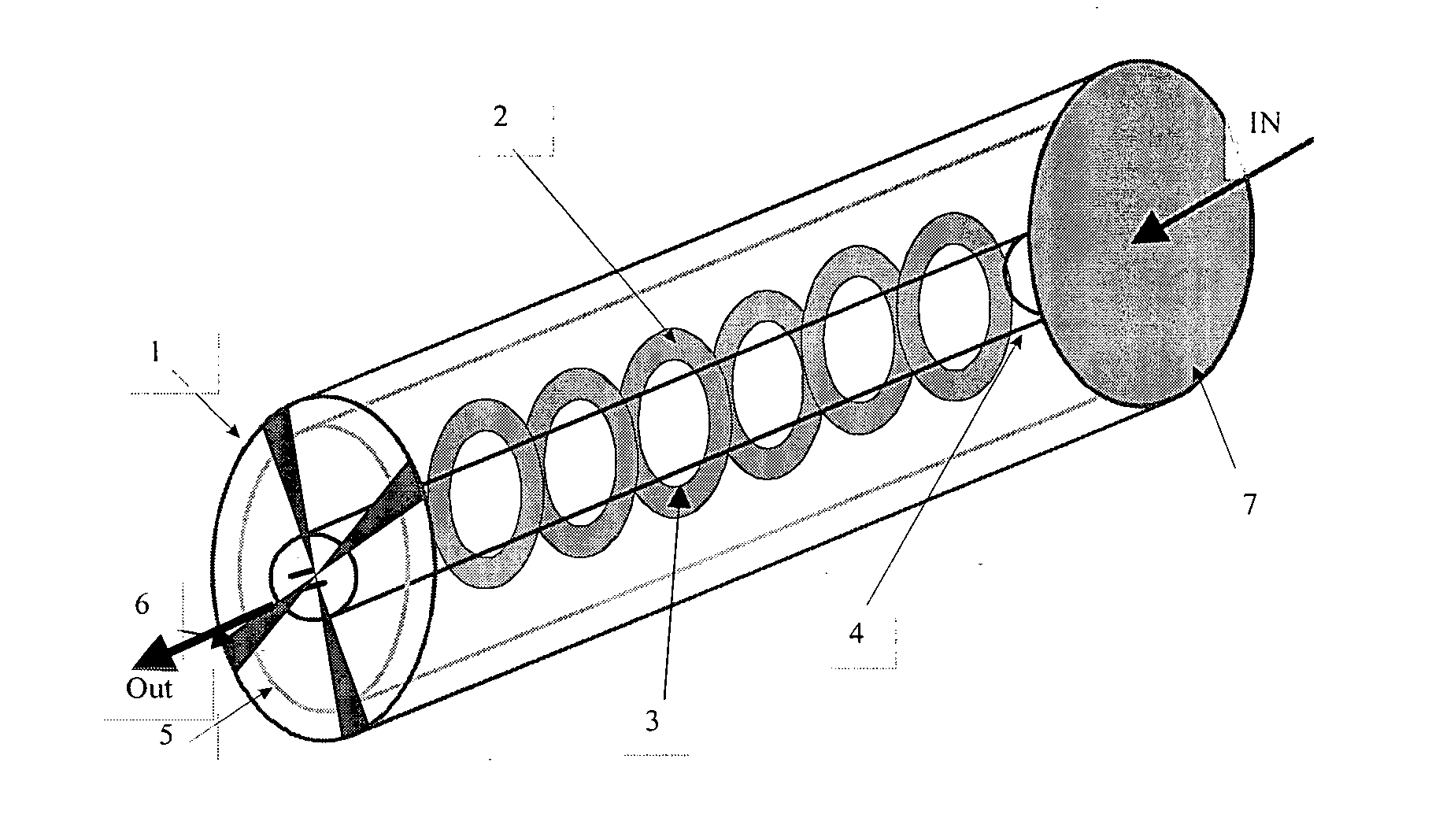
[0127] First Embodiment of the Device According to the Invention

[0128] This first embodiment is described with reference to the representation in perspective of FIG. 1. Rings (2) with an external diameter of 35 mm comprising a circular opening (3) with a diameter of 15 mm at their center are first obtained by cutting out either aluminum sheets with a thickness of 100 .mu.m degreased with methanol or filter papers (Whatman No. 5) and are then coated with catalyst in accordance with the method of example 1.

[0129] A cylindrical glass reactor (1) with a length of 25 cm and an internal diameter of 4 cm is equipped with rings (2)--six of which are represented in FIG. 1--acting as catalytic supports, placed along a source (4) composed of a fluorescent tube (UV A Cleo 15 watts, sold by Philips) with a diameter of 15 mm and separated from one another by approximately 12 mm. A reflector (5) can be installed against the internal wall of the reactor (1). A fan (6) and a filter (7) are placed at...

example 3

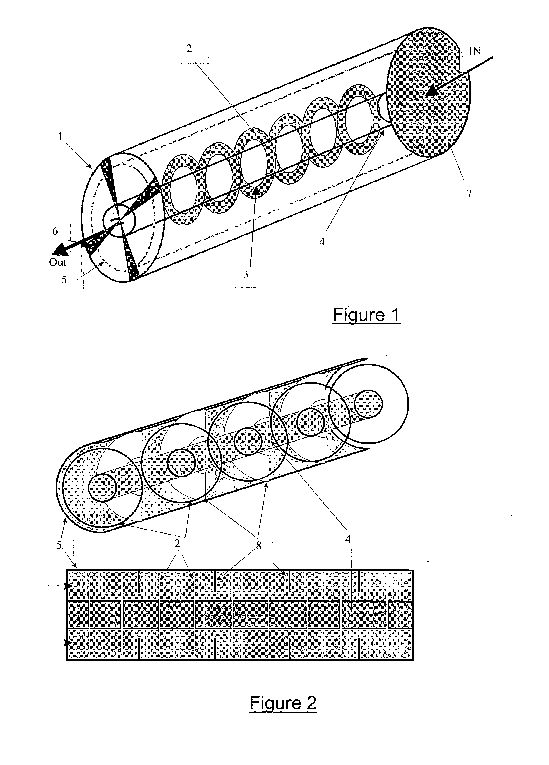
[0130] Second Embodiment of the Device According to the Invention

[0131] This second embodiment is described with reference to FIG. 2, which gives a representation in perspective (top view) and a longitudinal section (bottom view) of it. It comprises, in addition to the elements already present in FIG. 1, indicated by the same numbers and with the same dimensions as in example 2, baffles (8) formed of rings with an external diameter of 4 cm for an internal opening with a diameter of 2 cm. These baffles (blocking means) are inserted every two rings (2) and are in direct contact with the wall of the reactor (1). A fan (6) and a filter (7) (not represented in FIG. 2) can be placed at the ends of the reactor (1) as in example 2.

example 4

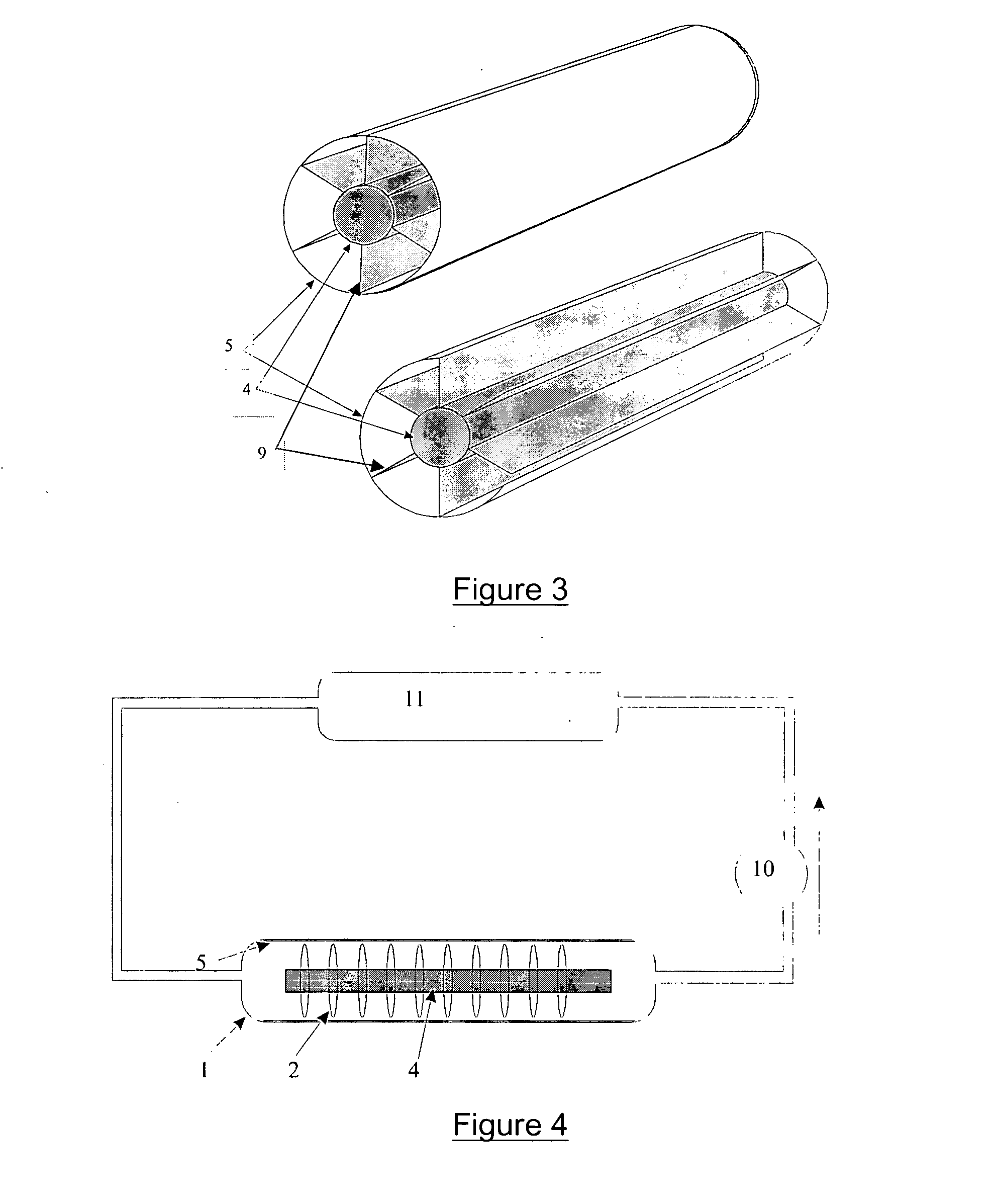
[0132] (Comparative)--Device According to the Prior Art

[0133] A reactor with the same external dimensions as that of examples 2 and 3 and in accordance with U.S. Pat. No. 5,790,934 is described with reference to FIG. 3, which gives a representation in perspective with transverse section (top view) and a representation in open perspective (bottom view) of it. Comprising the elements already present in FIG. 1 and represented by the same numbers, it is obtained by replacing the rings (2) with six equidistant (that is to say, forming an angle of 60 degrees with one another) longitudinal fins (9) positioned radially with respect to the tube (4) and occupying the entire space between the tube (4) and the reflector (5) applied against the internal face of the reactor (1). A fan (6) and a filter (7) (not represented in FIG. 3) can be placed at the ends of the reactor (1) as in example 2.


PUM

PropertyMeasurementUnit
angleaaaaaaaaaa
flow ratesaaaaaaaaaa
wavelengthsaaaaaaaaaa

Abstract

The invention concerns a device for purifying a gas effluent containing contaminants, comprising: a reactor including at least an inlet for the gas to be purified and at least an outlet for the purified gas ; at least an ultraviolet or visible radiation source; and at least a support element arranged inside the reactor and coated with a catalyst forming an exposed catalytic surface capable of oxidising at least partly the contaminants under the action of the ultraviolet or visible radiation. The reactor comprises at least two obstructing means, each of said obstructing means obstructing partly the flow of the gas effluent from said inlet up to said outlet and generating a turbulent gas zone on its downstream side, and a catalytic surface is arranged in each turbulent gas zone so that the turbulent gas flow is incident on said catalytic surface. The invention is applicable to disinfection and pollution management of air and industrial gases.

Description

[0001] This application is a continuation-in-part of International Application No. PCT / EP01 / 14742 filed Dec. 13, 2001, which was published in French, and which claims the benefit of European patent Application No. 00870303.5 filed Dec. 15, 2000; the disclosures of which are incorporated by reference in their entirety.[0002] The present invention relates to a process for the purification of gaseous effluents and to a device, assembled or in kit form, for the implementation of this process. More generally, the invention relates to the field of the decontamination of gases, in particular to the purification and the reduction in pollution of the air. The invention also relates to the preservation of agricultural products.STATE OF THE ART[0003] There exists a general need to remove atmospheric pollutants in a fast, certain and economical way. The term "pollutants" is understood here as meaning contaminants, in particular gaseous contaminants, the undesirable nature of which can be due to...

Claims


Application Information

Patent Timeline
Patent Type & Authority Applications(United States)
IPC IPC(8): B01D53/86
CPCB01D2255/802B01D53/86
Inventor KARTHEUSER, BENOITMAY, BRONISLAV HENRIDESPRES, JEAN-FRANCOIS
Owner UNIVERSITE CATHOLIQUE DE LOUVAIN
Why Eureka
Try Eureka