
Current supplying circuit

Active Publication Date: 2004-03-04
DAICEL CHEM IND LTD
View PDF6 Cites 6 Cited by
  • Summary
  • Abstract
  • Description
  • Claims
  • Application Information

AI Technical Summary

Benefits of technology

[0006] In order to reduce a total amount of an electric current stored in the capacitor, which is an essential condition to reduce a capacitance of the capacitor for backup power source provided in an ECU, the present inventors started studying in view of reducing an amount of ignition energy required for actuating individual igniters.
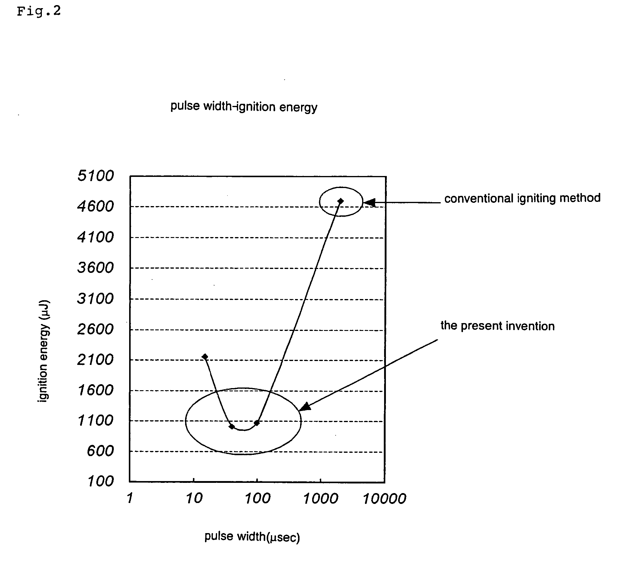
[0010] Therefore, in this invention, a current is supplied at a relatively high current value for a short time, that is, such that the width of the ignition pulse at this time is 20 to 500 .mu.sec, preferably 30 to 200 .mu.sec, and more preferably 40 to 100 .mu.sec. As a result, since the amount of ignition energy required for actuating individual igniters can be reduced, the amount of ignition energy required for all the igniters, namely, for the whole air bag system can be reduced. For this reason, a capacitance of a capacitor for backup power source incorporated into the ECU can be made smaller and therefore, the ECU itself can also be made compact.
[0017] By using an ignition pulse with such a specific width, an amount of current (an amount of ignition energy) required for actuating individual igniters can be reduced, so that an amount of current required for all igniters, namely for the whole air bag system, can be reduced. For this reason, a volume of a capacitor for backup power source incorporated into the ECU can be made smaller and therefore the ECU itself can also be made compact.
[0021] By using the current supplying circuit of the present invention, the weight of the whole air bag system mounted on a vehicle can be reduced while securing operation performance similar to that in the conventional one.

Problems solved by technology

However, this capacitor has to actuate all igniters, and therefore, the capacitor is obligated to have a large capacitance (namely, weight), which makes the ECU so large.

Method used


Image

  • Current supplying circuit
  • Current supplying circuit
  • Current supplying circuit

Examples


first embodiment

[0029] (1) First Embodiment

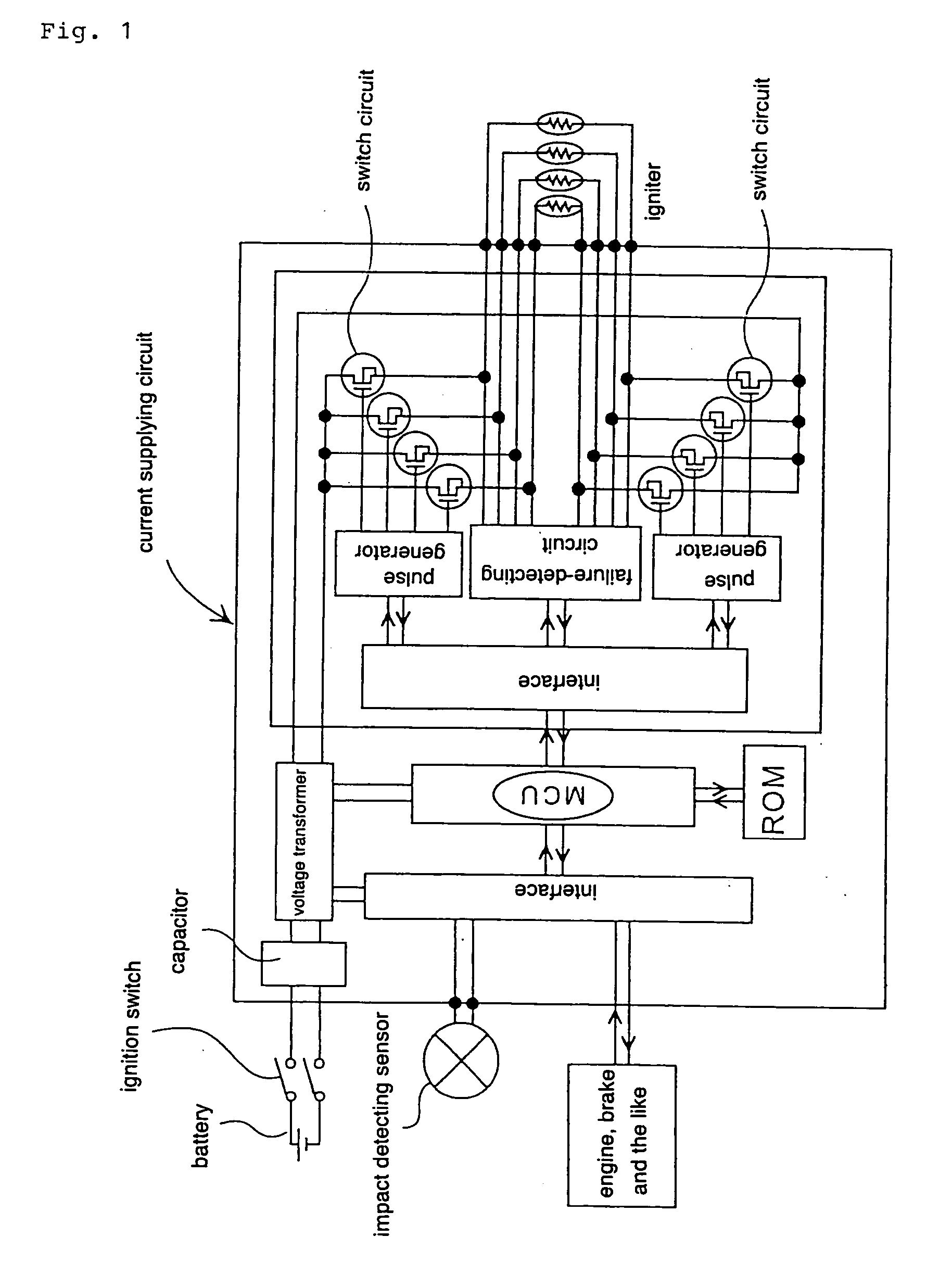
[0030] An embodiment of the present invention will be explained below with reference to the drawings. FIG. 1 is a conceptual diagram of a current supplying circuit of the present invention, and the current supplying circuit is provided in an ECU.

[0031] A current supplying circuit is constituted by arranging respective elements of at least a switch circuit, a pulse generator, a disconnection detecting circuit, a voltage transformer, a capacitor and the like on a substrate, and it is provided in a midway of a current path connecting a battery which is an external power source and igniters incorporated into gas generators. Two current paths are provided for each igniter and formed by two conducting wires (lead wires).

[0032] The switch circuit which opens or closes the current path and blocks a current when it is unnecessary to actuate an igniter to start supplying a current at a time of actuation of the igniter is provided in the current supplying circuit, an...

experimental example 1

[0042] A test circuit shown in FIG. 7 was used as the current supplying circuit, and it was recorded such that each switch circuit was supplied with currents supplied from the power source, being adjusted to have ignition pulses with widths of 15 .mu.sec, 40 .mu.sec, 100 .mu.sec and 2000 .mu.sec.

[0043] A general igniter shown in FIG. 3 was used as the igniter. In the igniter, the heat generating portion was constituted by connecting a metal thin wire, which was a resistance heat generating body (resistance=2 .OMEGA.), between electrodes by a resistance-welding, ZPP of 60 mg was used as the priming, and the heat generating portion and ZPP were maintained in a cup such that they were press-contacted with each other. The igniter were connected to conducting wires at two pin portions, and it was connected to a direct-current source via the current supplying circuit shown in FIG. 7.

[0044] Under these experimental conditions, the combustion state of the priming when a current was supplied...

second embodiment

[0049] (2) Second Embodiment

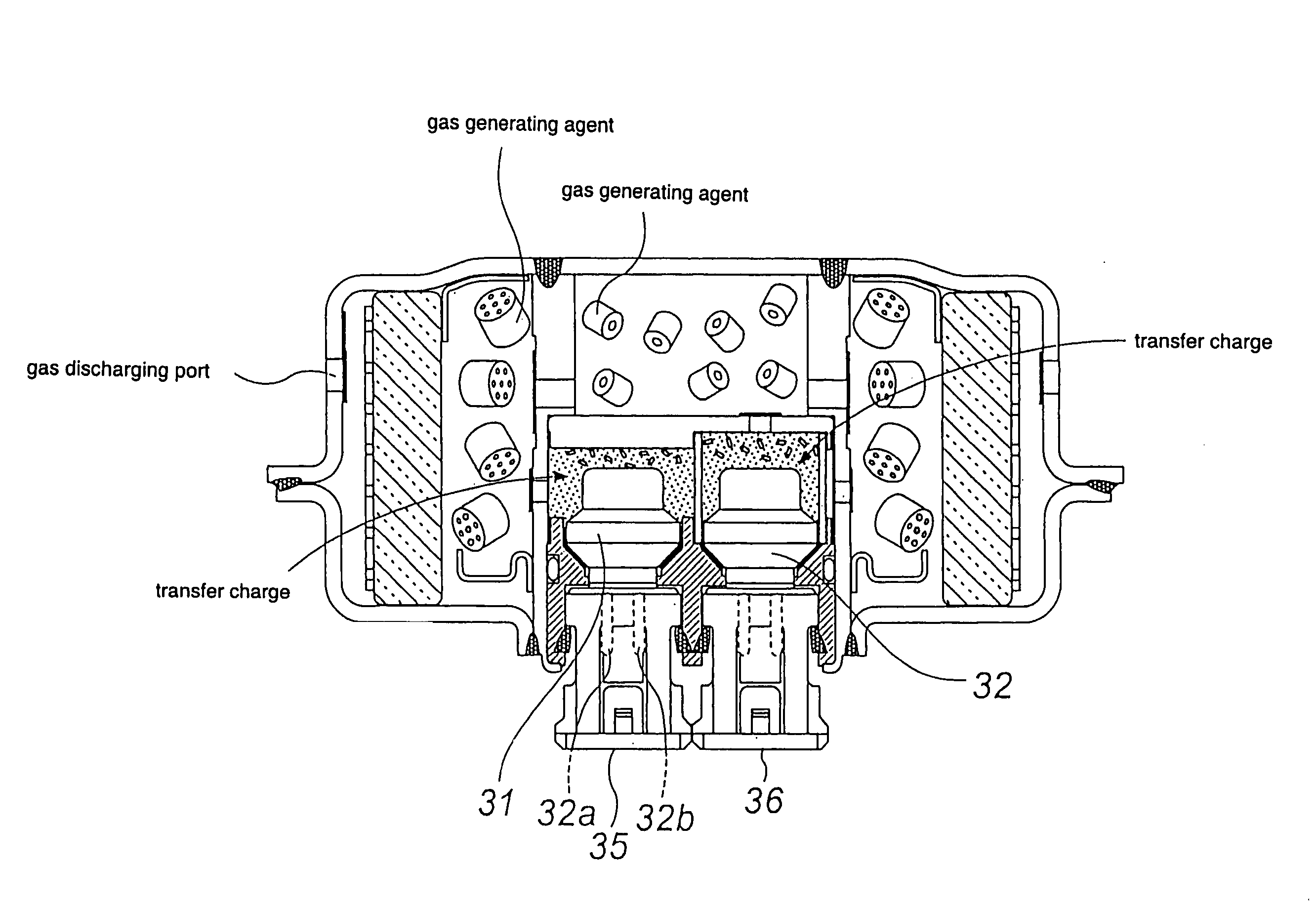
[0050] Next, an embodiment of an air bag system of the present invention using the above-described current supplying circuit will be explained with reference to FIG. 1 to FIG. 6. FIG. 5 and FIG. 6 are sectional views of general gas generators in the radial direction, FIG. 5 showing a gas generator of a single type having a single igniter, and FIG. 6 showing a gas generator of a dual type having two igniter.

[0051] As shown in FIG. 4, an air bag system mounted in a vehicle comprises an ECU connected to a power source (a battery) and an impact detecting sensor, and plural module cases accommodating plural gas generators and air bags, which is connected to the ECU, wherein each of the ECU and individual gas generators is connected separately by conductors, and the current supplying circuit as shown in FIG. 1 is provided in the ECU.

[0052] As the gas generator accommodated in the module case, one of the single type shown in FIG. 5 or one of the dual type shown ...


PUM

PropertyMeasurementUnit
Weightaaaaaaaaaa
Currentaaaaaaaaaa
Widthaaaaaaaaaa

Abstract

The present invention provides a current supplying circuit in which the weight of an air bag system is reduced. A current supplying circuit supplying a current required for actuating an electric igniter arranged in a gas generator at a time of actuation of the gas generator for an air bag, and comprising a switch circuit for opening or closing a current path for actuating the igniter, a pulse generator for providing a controlling pulse for opening or closing the switch circuit, and the switch circuit provided between the current path and an external power source, wherein a current obtained from the external power source is supplied as an ignition pulse for actuating the igniter by the switch circuit, and the current is further adjusted such that the width of the ignition pulse is 20 to 500 musec to be supplied.

Description

TECHNICAL FIELD TO WHICH THE INVENTION BELONGS[0001] The present invention relates to a current supplying circuit which supplies an electric current for actuating an igniter at a time of actuation of an air bag gas generator, an air bag system using the current supplying circuit and a method of actuating an igniter.PRIOR ART[0002] An air bag system for protecting a passenger from an impact at a time of collision of a vehicle is indispensable, and the air bag system needs to be reduced in weight from a demand for reducing weight of a whole vehicle. Recently, kinds and the total number of air bags such as an air bag for a driver side, an air bag for a passenger side next to the driver, an air bag for a rear seat side, and an air bag for an side impact are increasing, and therefore, a lighter air bag system is in greater demand.[0003] In a current air bag system, an electronic control unit (ECU) connected to a power source (a battery in a vehicle) and an impact detecting sensor are ind...

Claims


Application Information

Patent Timeline
IPC IPC(8): B60R21/01F42D1/045
CPCF42D1/045B60R21/017
Inventor OKAMOTO, MITSUYASUODA, SHINGO
Owner DAICEL CHEM IND LTD
Features
  • Generate Ideas
  • Intellectual Property
  • Life Sciences
  • Materials
  • Tech Scout
  • Unparalleled Data Quality
  • Higher Quality Content
  • 60% Fewer Hallucinations
Learn More