
Method and apparatus for a quadrupole transmitter for directionally sensitive induction tool

a directionally sensitive induction and quadrupole transmitter technology, applied in the direction of instruments, scientific instruments, measurement devices, etc., can solve the problems of inability to distinguish whether a layer is above or below the borehole, and the conductivity of the induction voltage measurement to be in error

Inactive Publication Date: 2004-03-11
BAKER HUGHES INC
View PDF2 Cites 25 Cited by
  • Summary
  • Abstract
  • Description
  • Claims
  • Application Information

AI Technical Summary

Benefits of technology

The present invention is about a method and apparatus for performing resistivity measurements in a wellbore using an electromagnetic induction tool. The invention provides a way to measure the electrical properties of the formation surrounding the wellbore in two different modes, which allows for more accurate geo-steering and bed boundary detection. The invention solves the problem of overlooking non-conductive layers in the formation that may be of commercial interest by interpreting the well log made using the electromagnetic induction resistivity well logging instruments known in the art. The invention includes a method for correcting the error caused by the relative dip angle between the bore-hole axis and the normal of the bedding plane. The technical effects of the invention include improved accuracy in geo-steering and bed boundary detection, as well as the ability to measure non-conductive layers in the formation.

Problems solved by technology

If the layers are not perpendicular to the axis of the instrument, the conductivity of the media surrounding the instrument can vary azimuthally, causing the inferences about the conductivity from the measurements of the induction voltage to be in error.
A limitation to the electromagnetic induction resistivity well logging instruments known in the art is that they typically include transmitter coils and receiver coils wound so that the magnetic moments of these coils are substantially parallel only to the axis of the instrument.
It is not possible to distinguish whether a layer is above or below the borehole from these data alone.

Method used


Image

  • Method and apparatus for a quadrupole transmitter for directionally sensitive induction tool
  • Method and apparatus for a quadrupole transmitter for directionally sensitive induction tool
  • Method and apparatus for a quadrupole transmitter for directionally sensitive induction tool

Examples


Embodiment Construction

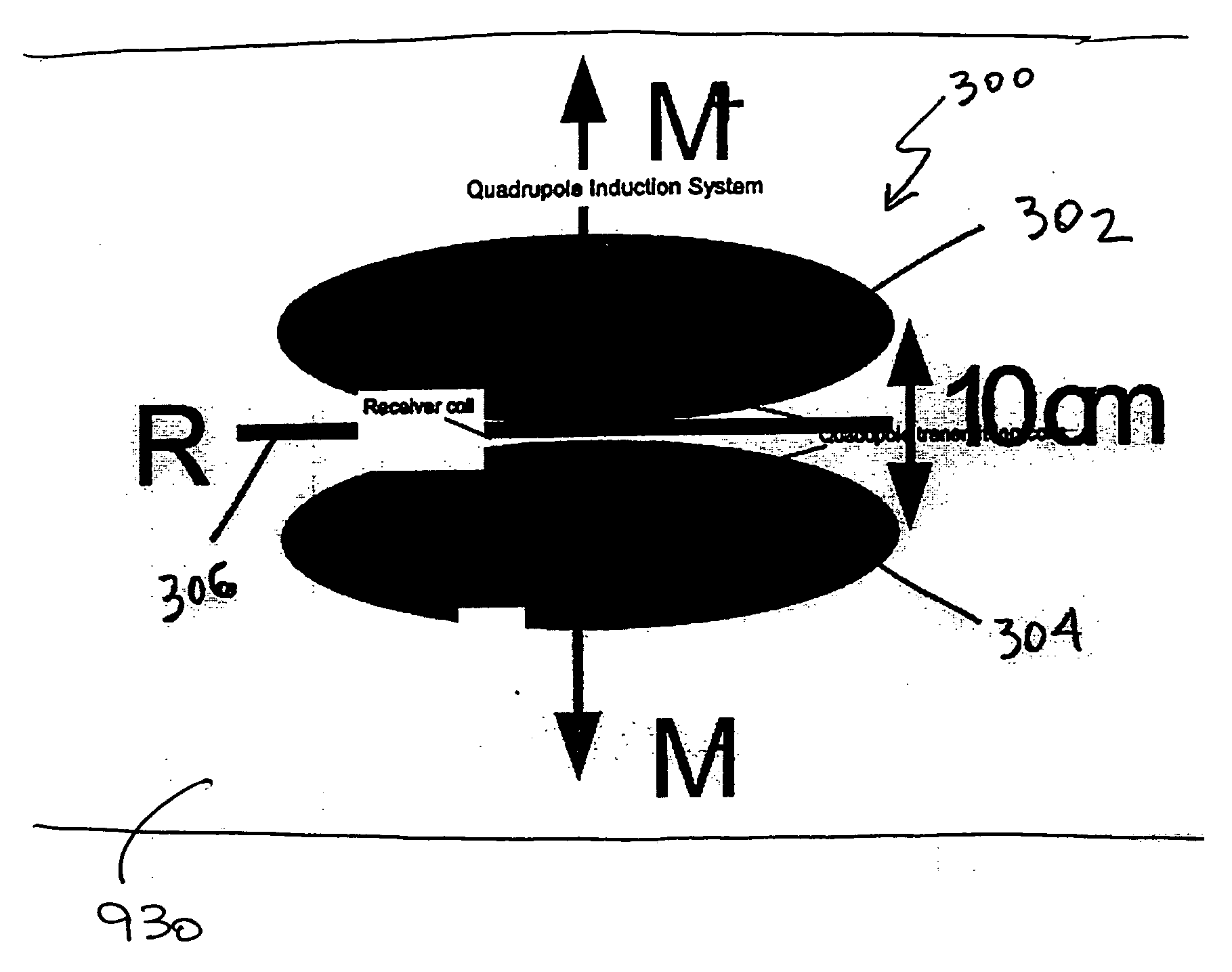
[0033] The present invention provides a method and apparatus for performing resistivity measurements with azimuthal resolution. The present invention provides for larger depth of investigation for resistivity (Rt) determination and bed boundary detection during reservoir navigation along with enhanced accuracy over a broad range of resistivities. The present invention provides MPR with resolving capability in azimuthal direction that leads to a increased and more effective usage of MPR for geo-steering.

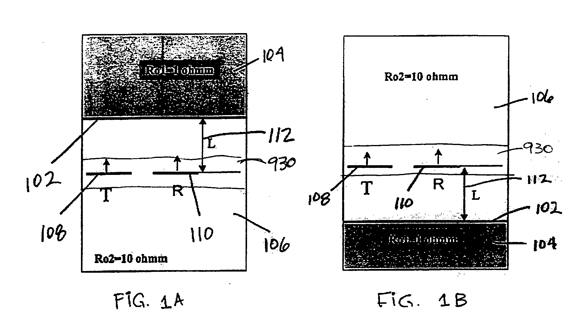
[0034] Turning now to FIG. 1, FIG. 1 illustrates a two-layered formation models with up / down boundary 102. Resistivities of the layers 106, 104, are .rho..sub.1=10 ohm-m and .rho..sub.2=1 ohm-m respectively. The excitation dipole 108 is oriented in the same direction as receiving dipole 110. The tool (not shown) is placed at a different distance L, containing dipoles 108, 110 from the boundary 102 inside the resistive layer. The tool traverses a bore hole 930 considered to be horizont...


PUM


Abstract

The present invention provides a method and apparatus for performing resistivity measurements for the purpose of geo-steering with 180-degree azimuth resolution. All the measurements represent a complementary set of data acquired in two operational modes. The directional mode providing sensitivity of the received signals to the azimuth characteristics of the formation. The deep mode provides a large depth of investigation for resistivity determination and bed boundary detection. The directional mode can be implemented using one receiving coil placed in between quadruple type transmitter. The deep mode represents either array induction measurements or multiple propagation resisitivity (MPR) measurements that provide high depth of investigation for resistivity determination and bed boundary detection.

Description

[0001] The patent application claims priority from U.S. patent application Ser. No. 10 / 338,871 filed on Mar. 14, 2003 entitled "A Method and Apparatus for a Quadrupole Transmitter for Directionally Sensitive Induction Tool" by G. Itskovich, A. Bespalov and B. Chakarov.[0002] 1. Field of the Invention[0003] The present invention pertains to the field of performing resistivity measurements for the purpose of geo-steering in two operational modes. A directional mode provides sensitivity of the received signals to the azimuthal characteristics of the formation and a deep mode provides large depth of investigation for resistivity determination and bed boundary detection relative to the borehole and tool.[0004] 2. SUMMARY OF THE RELATED ART[0005] Electromagnetic induction and wave propagation logging tools are commonly used for determination of electrical properties of formations surrounding a borehole. These logging tools give measurements of apparent resistivity (or conductivity) of the...

Claims


Application Information

Patent Timeline
Patent Type & Authority Applications(United States)
IPC IPC(8): G01V3/28
CPCG01V3/28G01V3/30
Inventor ITSKOVICH, GREGORYBESPALOV, ALEXANDERTCHAKAROV, BORISLAV J.
Owner BAKER HUGHES INC
Learn More