

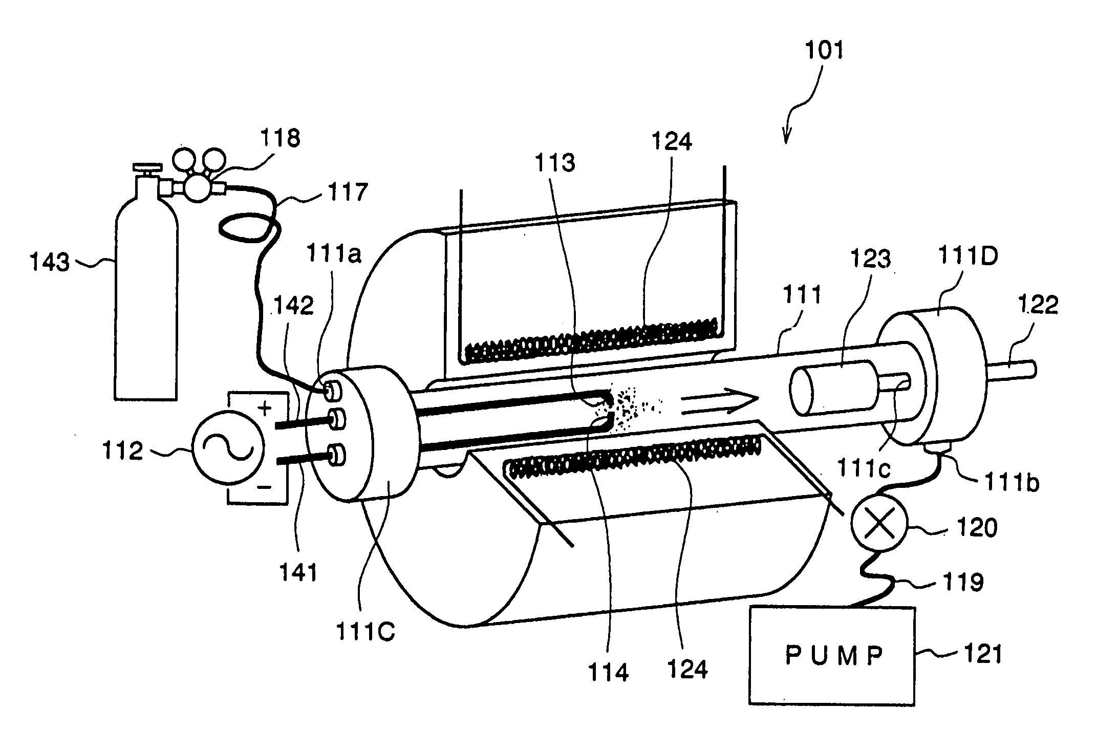
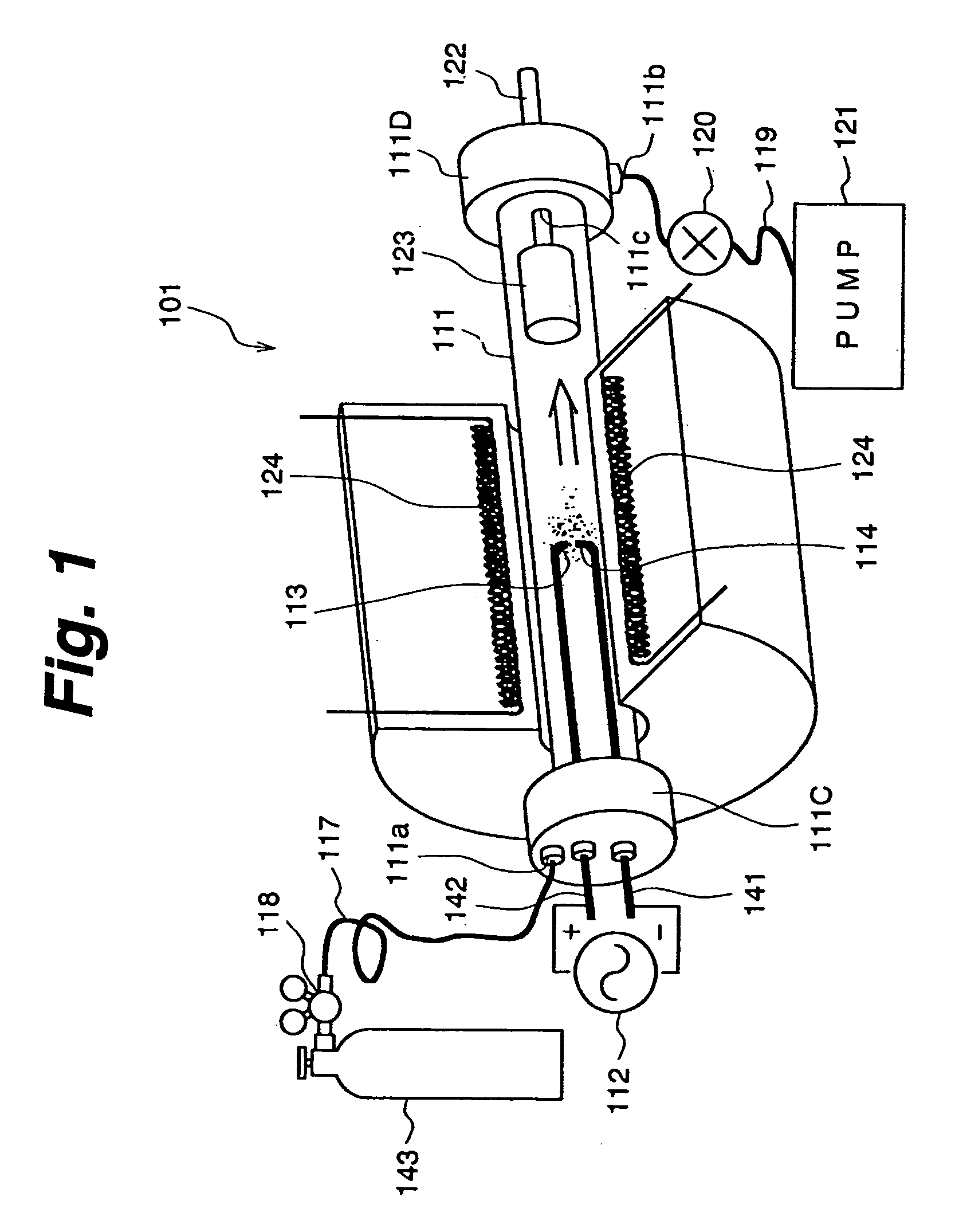
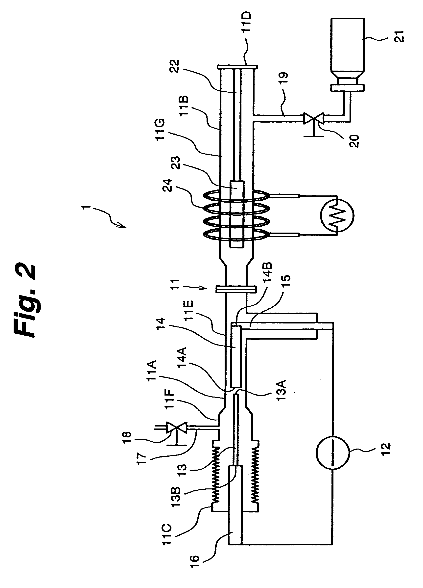
Device and method for manufacture of carbonaceous material
a carbonaceous material and manufacturing method technology, applied in the manufacture of nanostructures, chemical/physical/physical-chemical processes, energy-based chemical/physical/physical processes, etc., can solve the problems of difficult to obtain high-purity single-walled carbon nanotubes substantially free from catalysts, difficult to remove metal catalysts, etc., to achieve efficient convergent organic gas, reduce the effect of impurities
- Summary
- Abstract
- Description
- Claims
- Application Information
AI Technical Summary
Benefits of technology
Problems solved by technology
Method used
Image

Examples
Embodiment Construction
was prepared under the same conditions as those used to prepare Invention 1 except that the carbonaceous materials accumulating on the capturer 23 were recovered without the heating process. Comparative Example 2 was prepared under the same conditions as those used to prepare Invention 1 except that the anode was a composite rod made of metal powder and carbon to have the composition of Co=1.2%, Ni=1.2% and C=97.6% and that the carbonaceous materials accumulating on the capturer 23 were recovered without the heating process.
[0083] Since Inventions 1 through 4 are different from Inventions 5, 6 and Comparative Example 2 in composition of the anode of the carbonaceous material manufacturing apparatus, Inventions 1 through 4 are compared with Comparative Example 1 whereas Inventions 5 and 6 are compared with Comparative Example 2. Carbonaceous materials obtained in Inventions 1 to 6 and Comparative Examples 1, 2 were evaluated with a thermogravimetric device. For this thermogravimetric...
PUM
| Property | Measurement | Unit |
|---|---|---|
| Pressure | aaaaa | aaaaa |
| Angle | aaaaa | aaaaa |
| Diameter | aaaaa | aaaaa |
Abstract
Description
Claims
Application Information