Fuel cell for powering electronic appliances, in particular portable objects

a technology for electronic appliances and fuel cells, which is applied in the direction of cell components, cell component details, electrochemical generators, etc., can solve the problems of design constraints, inability to recharge batteries, and long charging operation of batteries

Inactive Publication Date: 2004-04-08
COMMISSARIAT A LENERGIE ATOMIQUE ET AUX ENERGIES ALTERNATIVES
View PDF1 Cites 14 Cited by
  • Summary
  • Abstract
  • Description
  • Claims
  • Application Information

AI Technical Summary

Benefits of technology

0039] c) easily reversible means for mechanical connection to the appliance to be powered.
0040] It should be noted that the assembly between the support and the appliance is tight, the appliance or alternatively the support comprising for example tightness means to confine the support inside the hydrogen expansion chamber arranged in the appliance.

Problems solved by technology

This results in designers being subjected to the constraint of having to find a compromise between the autonomy time of the equipment and the space and weight set aside for the battery.
It should however be noted that charging these batteries remains a long operation and requires the use of a removable accessory, or charger; this accessory imposes an additional constraint since the user has to keep it close at hand, otherwise he will be unable to recharge the battery.
However, this solution presents the drawback of involving prohibitive operating costs of the electronic appliance.
Furthermore, the disposable nature of these means, which comprise toxic materials, also gives rise to inopportune waste treatment costs.
Conditioning the hydrogen used for these fuel cells gives rise to a problem.
This results in these fuel cells being difficult to transpose for power supply of portable electronic appliances, wherein they have to be embedded, due either to a difficulty in matching the water reserve and the appliance or to an incompatibility between the hydrogen production or storage means and the constraints proper to portable appliances.

Method used


Image

  • Fuel cell for powering electronic appliances, in particular portable objects
  • Fuel cell for powering electronic appliances, in particular portable objects
  • Fuel cell for powering electronic appliances, in particular portable objects

Examples


Embodiment Construction

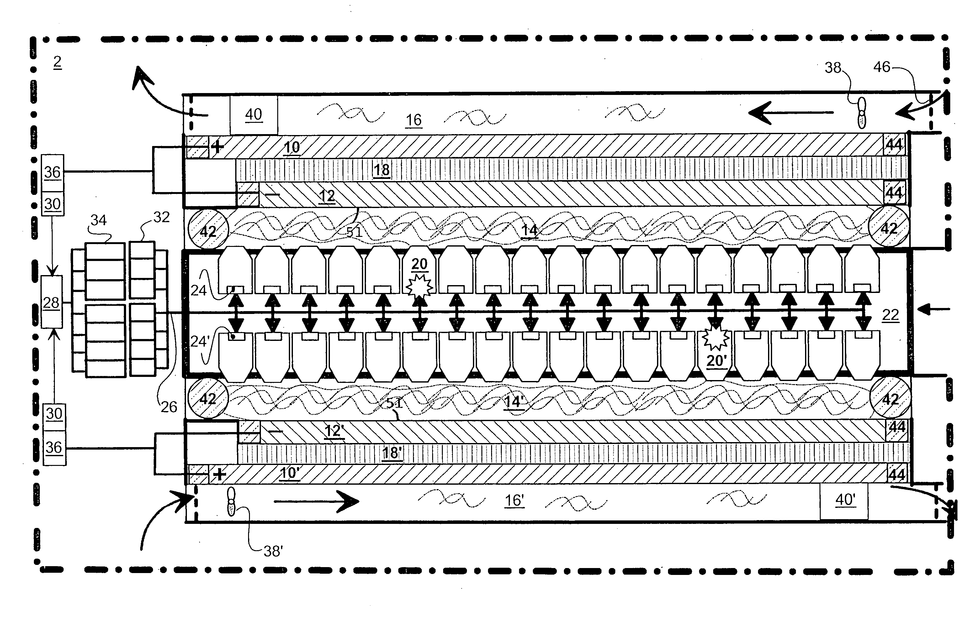
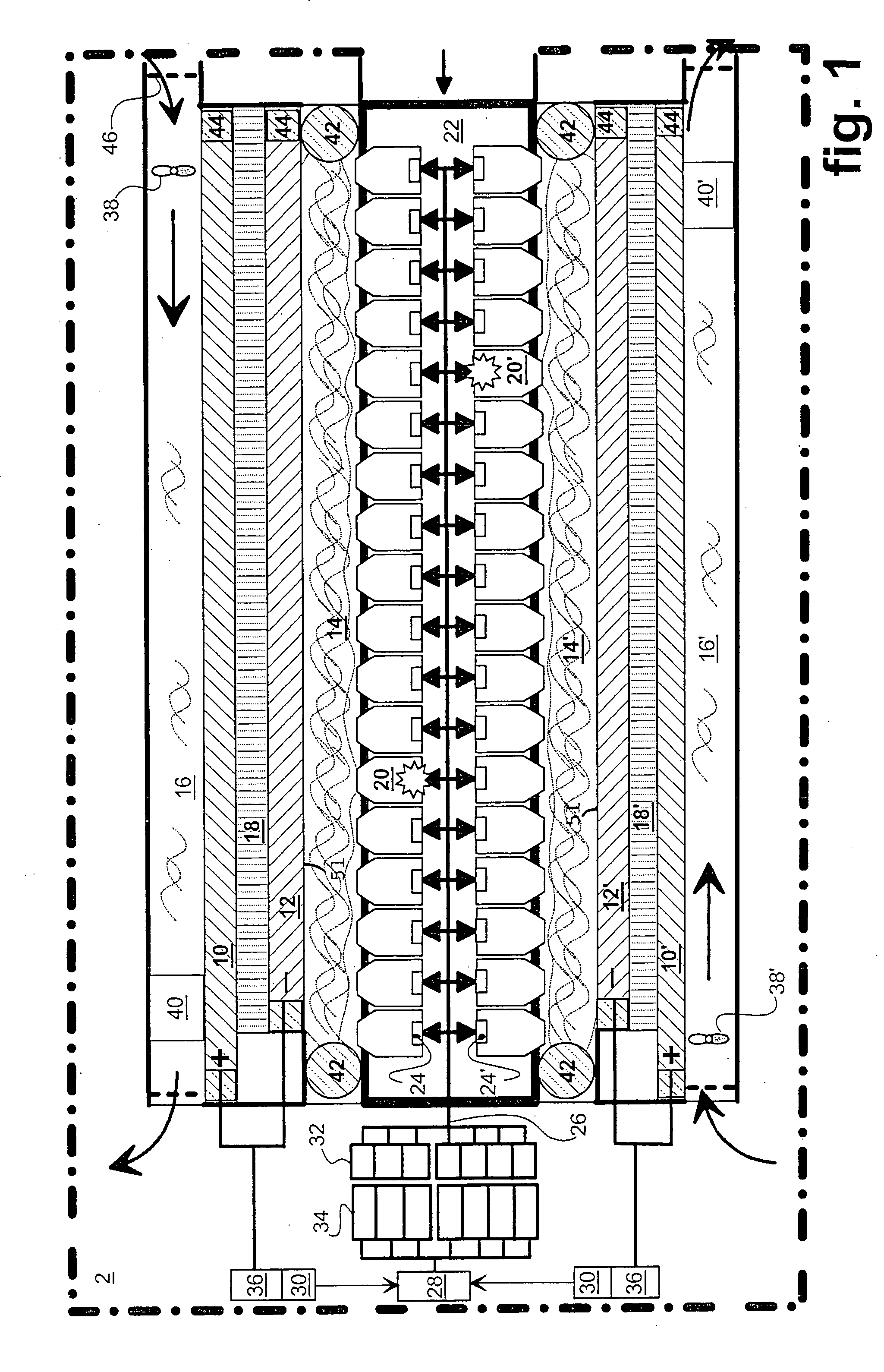
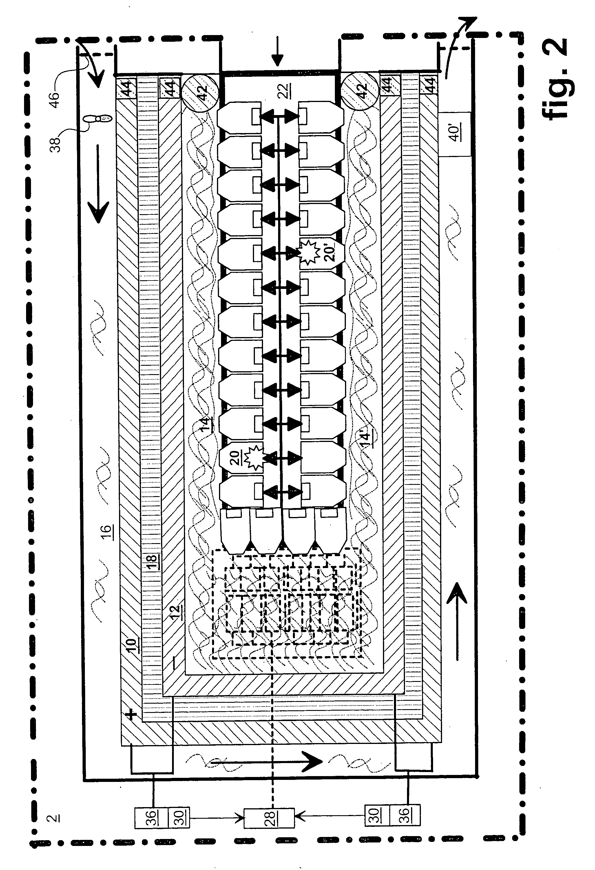
[0047] In the figures, a fuel cell designed to equip a portable electronic apparatus 2 can be seen. At least one anode 12,12' is in contact with the internal volume of a hydrogen expansion chamber 14,14' whereas at least one cathode 10,10' is in contact with the internal volume of an air flow chamber 16,16' that contains oxygen. At least one electrolyte 18,18' is interposed between each anode and cathode couple 10,12 and 10',12'.

[0048] A set of solid hydrogen storage bodies such as 20,20' are arranged in a middle zone forming a compartment 22. Ignition means 24,24' are assigned to each of these bodies 20,20' for selective combustion thereof by activating means 26 controlled by addressing means 28. These addressing means 28, comprised in the electronic means of the appliance 2 to be powered, are themselves placed under the control of means 30 for measuring the power available for the appliance.

[0049] The solid hydrogen storage bodies 20,20' release gaseous hydrogen by slow combustion...


PUM

PropertyMeasurementUnit
thicknessaaaaaaaaaa
timeaaaaaaaaaa
electrical poweraaaaaaaaaa

Abstract

The fuel cell (2) is of the kind comprising an anode (12) and a cathode (10) between which an electrolyte (18) is interposed. Solid bodies (20) storing a hydrogen mass, able to be decomposed by combustion, are associated to pyrotechnic means (24,26) to release the hydrogen and bring it into contact with the anode (12). Means (38) tap the ambient air to bring it into contact with the cathode (10). Firing of the pyrotechnic means (24,26) is placed under the control of addressing means (28) embedded in the appliance (2). The surplus water produced by the exchange between the hydrogen and the oxygen is resorbed by the temperature increase induced by combustion of the bodies (20). The solid bodies (20) are supported by an interchangeable card (22).

Description

[0001] The invention relates to the field of autonomous devices for providing electrical power. The object of the invention is to achieve such a device, that is consumable, for portable electronic appliances, for example mobile phones or such like, or equipment with an electronic memory or the like.[0002] It relates more particularly to a consumable device for providing electrical power designed for a portable electronic appliance and comprising a fuel cell comprising an electrolyte arranged between an anode and a cathode, means for storing hydrogen, means for conveying the stored hydrogen to the anode, means for tapping ambient air and for bringing the tapped air into contact with the cathode, means for controlling release of the hydrogen and means for neutralizing the surplus water produced by the cell.STATE OF THE TECHNIQUE[0003] One of the objectives of designers of portable electronic appliances resides in the light nature and small dimensions of these appliances, in particular...

Claims


Application Information

Patent Timeline
Patent Type & Authority Applications(United States)
IPC IPC(8): H01M2/10C01B3/00H01M8/00H01M8/04119H01M8/0606H01M8/065
CPCH01M2/1022H01M8/00H01M8/04156Y02E60/50H01M8/065H01M2300/0082Y02E60/324H01M8/0606Y02E60/32Y02E60/10
Inventor BLOCH, DIDIERDELAPIERRE, GILLESPRIEM, THIERRYMARSACQ, DIDIERLAURENT, JEAN-YVESGAUTHIER, CORRINEPERUT, CHRISTIAN
Owner COMMISSARIAT A LENERGIE ATOMIQUE ET AUX ENERGIES ALTERNATIVES
Why Eureka
Try Eureka