

Shoe with elastic sole
a technology of elastic soles and shoes, applied in the field of shoes with elastic soles, can solve the problems of inconvenient use, inconvenient use, and hardly satisfy the requirement for shoes with high elastic effect, and achieve the effects of better elasticity, better ventilation and elasticity, and better elasticity
Inactive Publication Date: 2004-04-15
WANG GUOHUA
View PDF9 Cites 40 Cited by
- Summary
- Abstract
- Description
- Claims
- Application Information
AI Technical Summary
Benefits of technology
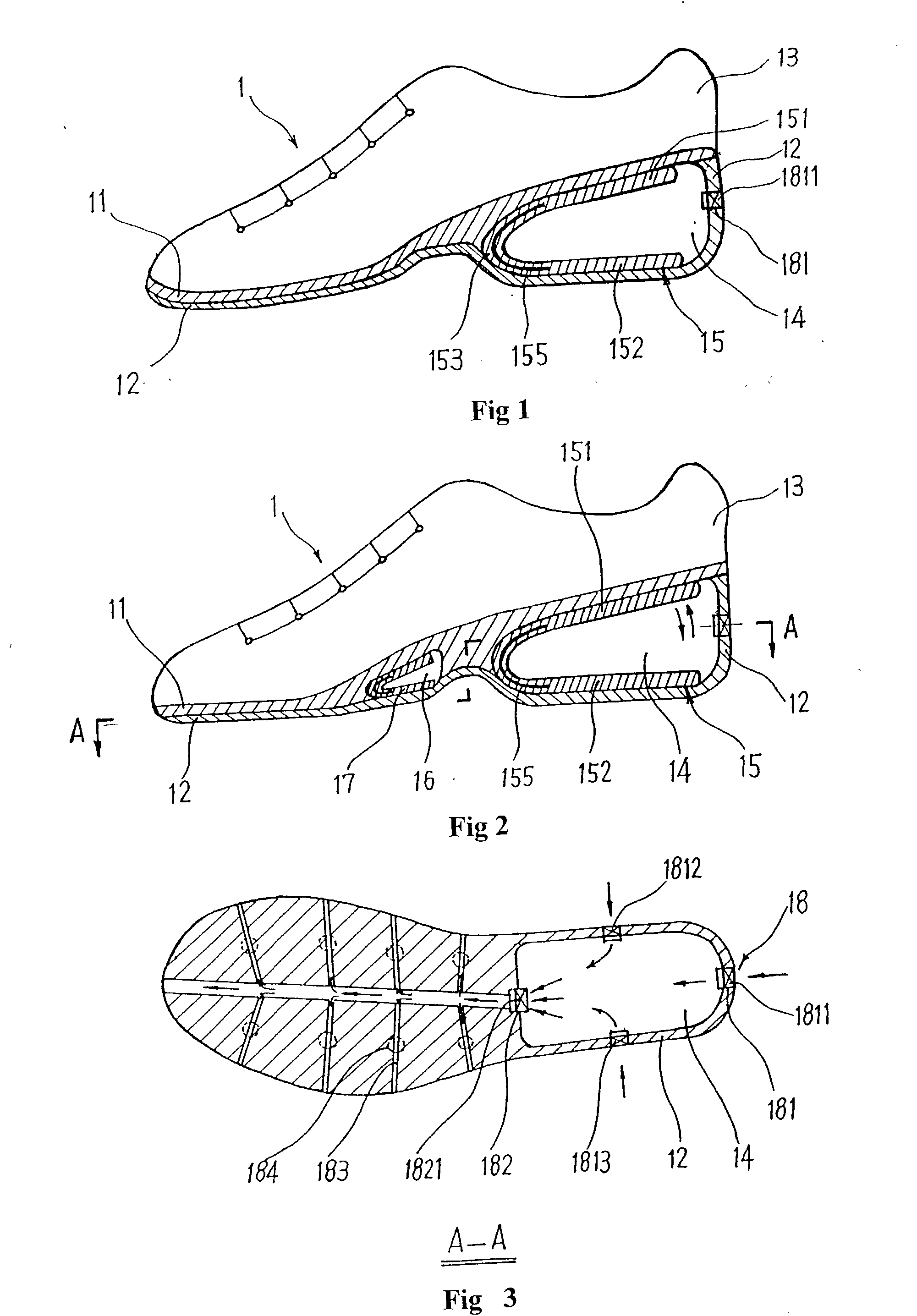
[0067] FIG. 1 shows one embodiment of the present invention. Shoe 1 comprises an inner sole 11, an outer sole 12 and an upper 13. A U-shaped cavity 14 with openings at the two lateral sides is provided in the heel portion of the shoe, in which a U-shaped spring pad 15 is located between the inner sole 11 and outer sole 12. A shoe with high elastic sole can be achieved by the high elastic structure formed by the U-shaped spring pad 15, which is structurally simple and easy to produce.
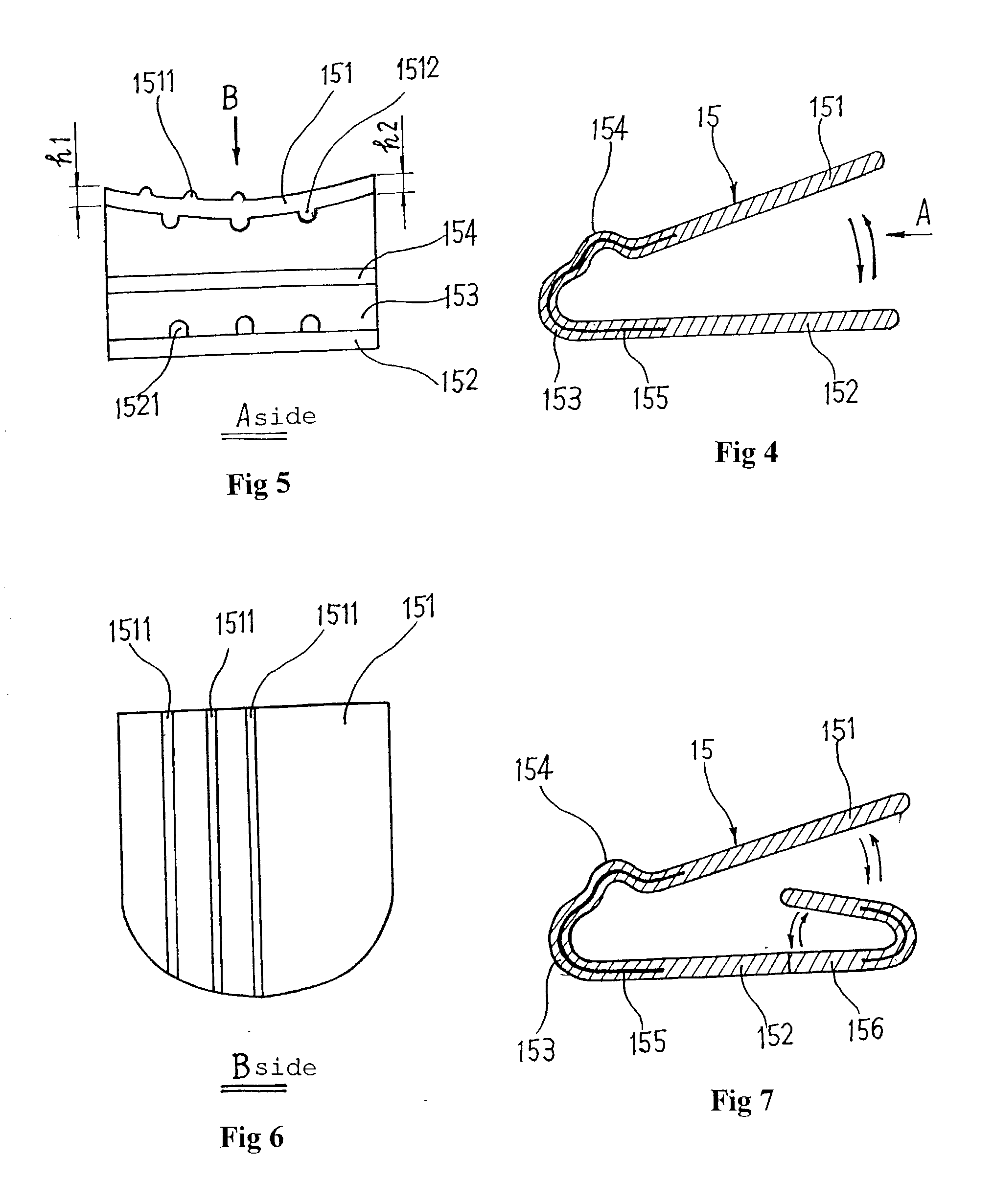
[0079] FIG. 7 shows yet another embodiment of the present invention, which has a similar structure to that of the second embodiment of the present invention. The difference is that the tail of said lower plate 152 can be connected with another U-shaped spring pad 156 forming a bi-directional structure of the U-shaped spring pad. The structure of the U-shaped spring pad 156 can be same to that of said U-shaped spring pad 15; therefore it is unnecessary to go in to details. This structure will provide further more elasticity and more smoothness of the reciprocating motions of the elastic sole because the elastic force of the U-shaped spring pad 15 is further more enhanced.
Problems solved by technology
However, the soles of such kinds of shoes are mostly made of soft and flexible materials that have limited elastic effect, which can hardly satisfy the requirement for a shoe with high elastic effect.
Especially, after a period of use, the soles of such kind of shoes made of soft and flexible materials will lose the elastic effects because of wear, making it inconvenient and not practical to use.
However, because such elasticity is achieved by a very complicated mechanism such as column springs, it is difficult to produce and will result in high costs.
At the same time, said shoe is difficult to maintain and repair due to its complicated structure.
Obviously, there is really a need for improvement of this kind of shoe because it is not suitable for mass production by the footwear industry.
1. Said shoe produce low elasticity or spring effect because elasticity of said shoe is achieved by elastic plastic cubes 203 and 204, which do not provide high elasticity as required by the wearer. Obviously, there is room for further improvement.
2. Said shoe has a complicate sole structure that will result in relatively higher cost to produce. Elastic plastic cubes 203 and 204 are affixed between upper and lower parts of the U-shaped plastic pad 202, which are in turn affixed between the inner sole and the outer sole within the cavity 206. So such sole structure is difficult to produce and results in high production costs. In addition, said sole structure can be damaged by the impact by the motion of the foot of the wearer after some time of use, making it difficult to repair. Obviously, there is room for further improvement.
Although such kinds of elastic structures can achieve some elasticity to the soles as attempted by the inventor, they do not satisfy the needs for high elasticity, which is obviously caused by imperfection of the design of the previous elastic sole structures.
In order to provide a shoe that has a high elastic sole, the footwear industry has been racking their brains to find out a satisfactory solution without any practical results.
Conventional shoes with elastic soles do not have an effective high elastic structure, which is obviously a problem remaining to be solved as soon as possible.
As can be seen from the above, there are still many defects of the existing shoes with elastic soles that demand prompt solution.
Method used
View moreImage
Smart ImageViewing Examples

Examples
Embodiment Construction
are only examples of several preferred embodiments, they should not be construed as limitations on the scope of the invention. Other examples of changes, substitutions, and alterations are readily ascertainable by one skilled in the art and could be made without departing from the spirit and scope of the present invention.
Login to View More PUM
 Abstract
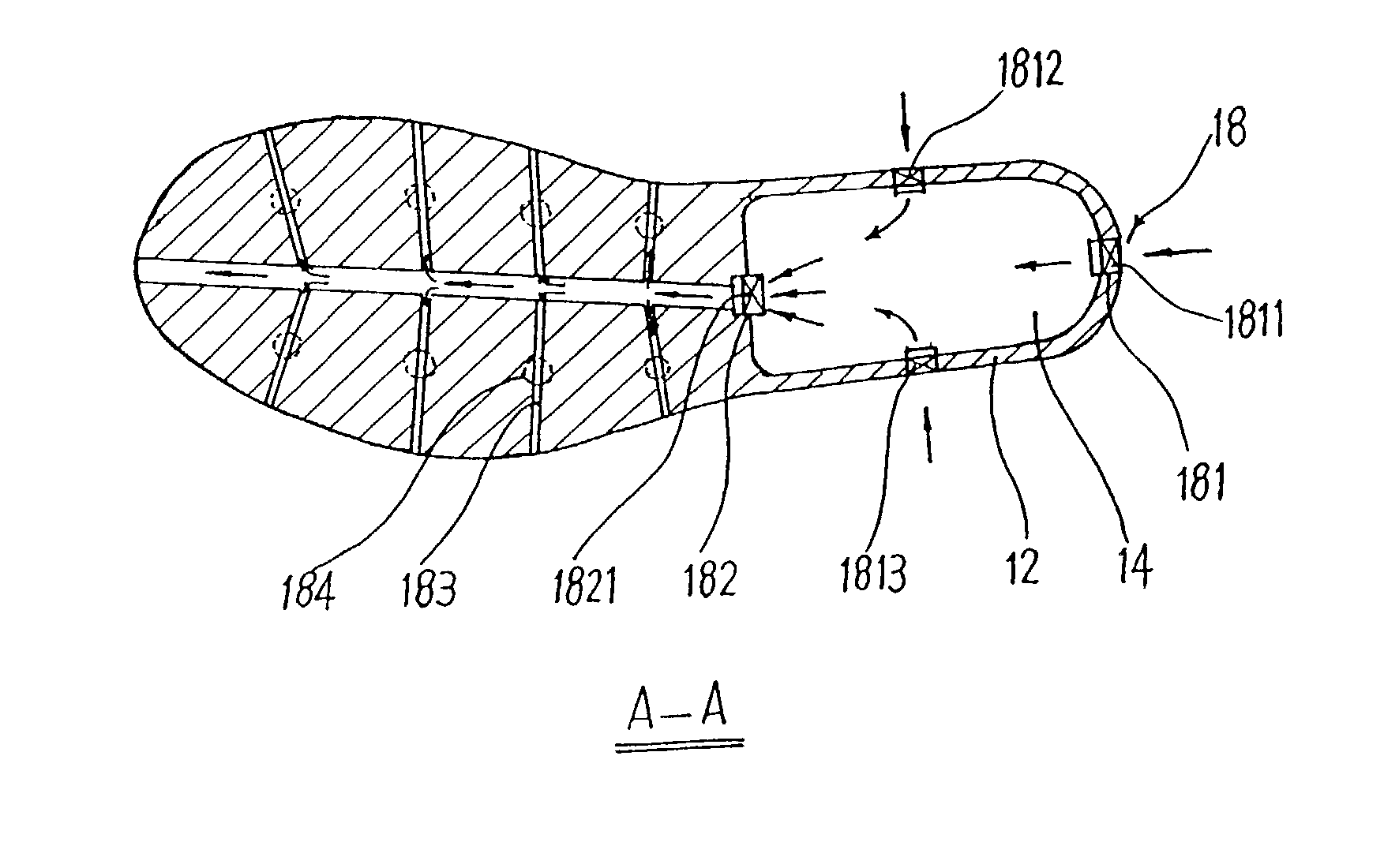
A shoe with elastic sole is disclosed. The shoe comprises an inner sole, an outer sole, an upper, and an elastic sole comprising a U-shaped cavity that has openings at the two lateral sides of the sole and a U-shaped spring pad made of carbon fiber plate provided in the cavity and between the inner sole and outer sole forming a highly elastic sole structure. A U-shaped spring tab is added to the core of the U-shaped portion of the U-shaped spring pad. Alternatively, the openings of the cavity at the two lateral sides of the sole can be closed, forming a totally enclosed cavity structure. Additionally, another U-shaped cavity with a U-shaped spring pad can be provided in the anterior portion of the sole, thus forming a sole structure with U-shaped spring pads both in the anterior and heel portion of the sole. A ventilation structure is provided between the inner sole and the outer sole. The vent structure comprises ventilation holes in the lateral and rear sides of the U-shaped cavity with check intake valves provided therein, and a ventilation hole in the front side of the U-shaped cavity with a check exhaust valve provided therein. The shoe has the advantages of large deformation and high elasticity during use that can provide comforts and forced ventilation with its simple structure that is suitable for manufacture by the footwear industry.
Description
[0001] 1. Field of the Invention[0002] The present invention relates to a shoe with elastic sole for personnel and daily use, and in particular, a shoe with elastic sole.[0003] 2. Background of the Invention[0004] With the improvement of the living conditions and change of life style, people are continuously seeking more comforts of shoes for daily use. Particularly, because people are attaching more and more importance to health improving exercises, there is a need for a kind of shoe that has a sole that can provide good cushioning during the course of health improving exercises. In order to satisfy such requirement, the footwear industry has developed numerous shoes of different kinds, mostly athletic shoes, which have spring cushioned soles to make the shoes comfortable to wear during normal walking and health improving exercises.[0005] Existing shoes with elastic soles have witnessed changes of structures on various aspects depending on different mechanisms attempted by inventor...
Claims
Login to View More Application Information
Patent Timeline
 IPC IPC(8): A43B13/18A43B13/20A43B21/28A43B21/30
CPCA43B1/0018A43B3/0063A43B13/183A43B21/30A43B13/203A43B13/206A43B21/285A43B13/187
InventorWANG, GUOHUA
OwnerWANG GUOHUA