Stackable weight system

a weight system and stackable technology, applied in the field of stackable weight systems, can solve the problems of prone to collapse of the vertical column of multiple stackable plates on top of one another, difficult balance and control, and dangerous handling

Inactive Publication Date: 2004-04-15
LANDFAIR CRAIG D
View PDF6 Cites 34 Cited by
  • Summary
  • Abstract
  • Description
  • Claims
  • Application Information

AI Technical Summary

Benefits of technology

0009] Stackable weight plates comprised of a front and a rear lateral faces with a protrusion at a proximal radial center of the front lateral face and corresponding recess at a proximal radial center of the rear lateral face is provided. The rear lateral face with the recess section at the proximal radial center of a top weight plate in a stack rests (or is stacked) on the front lateral

Problems solved by technology

Inherent to most weight training equipment is the fact that they are bulky, difficult to balance and control, and dangerous to handle as the amount of weight increases since users handling them can easily lose control and drop the devices, especially when they have exercised for a while and are fatigued.
Although floor stacking (or storage) of weight plates is more space efficient, the vertical column of multiple stacked plates on top of one another tends collapse.
The protruding end

Method used


Image

  • Stackable weight system
  • Stackable weight system
  • Stackable weight system

Examples


Embodiment Construction

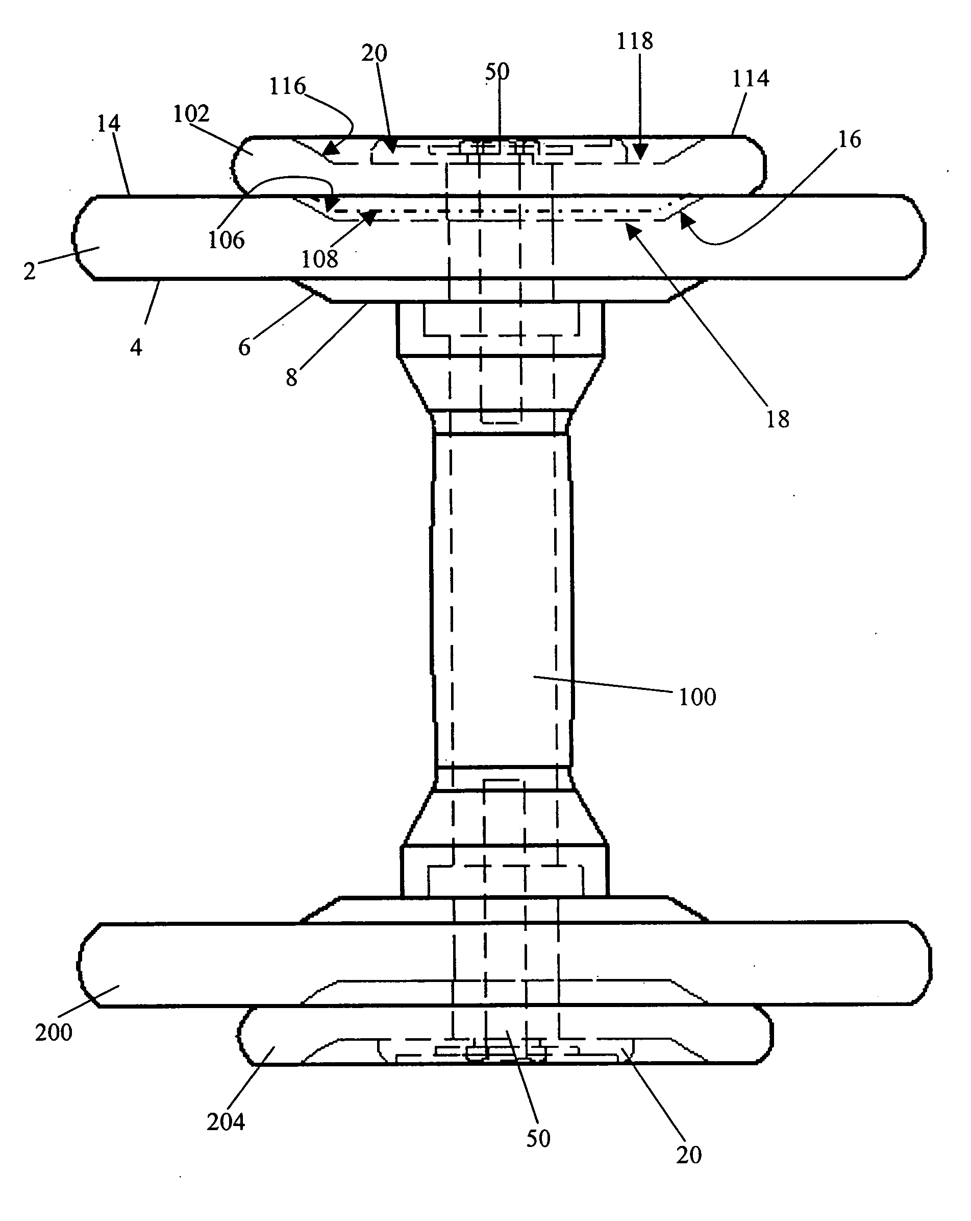
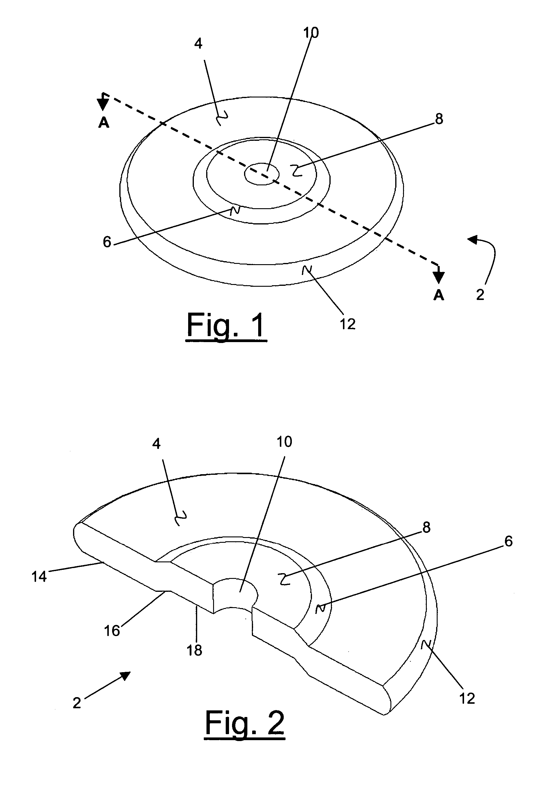
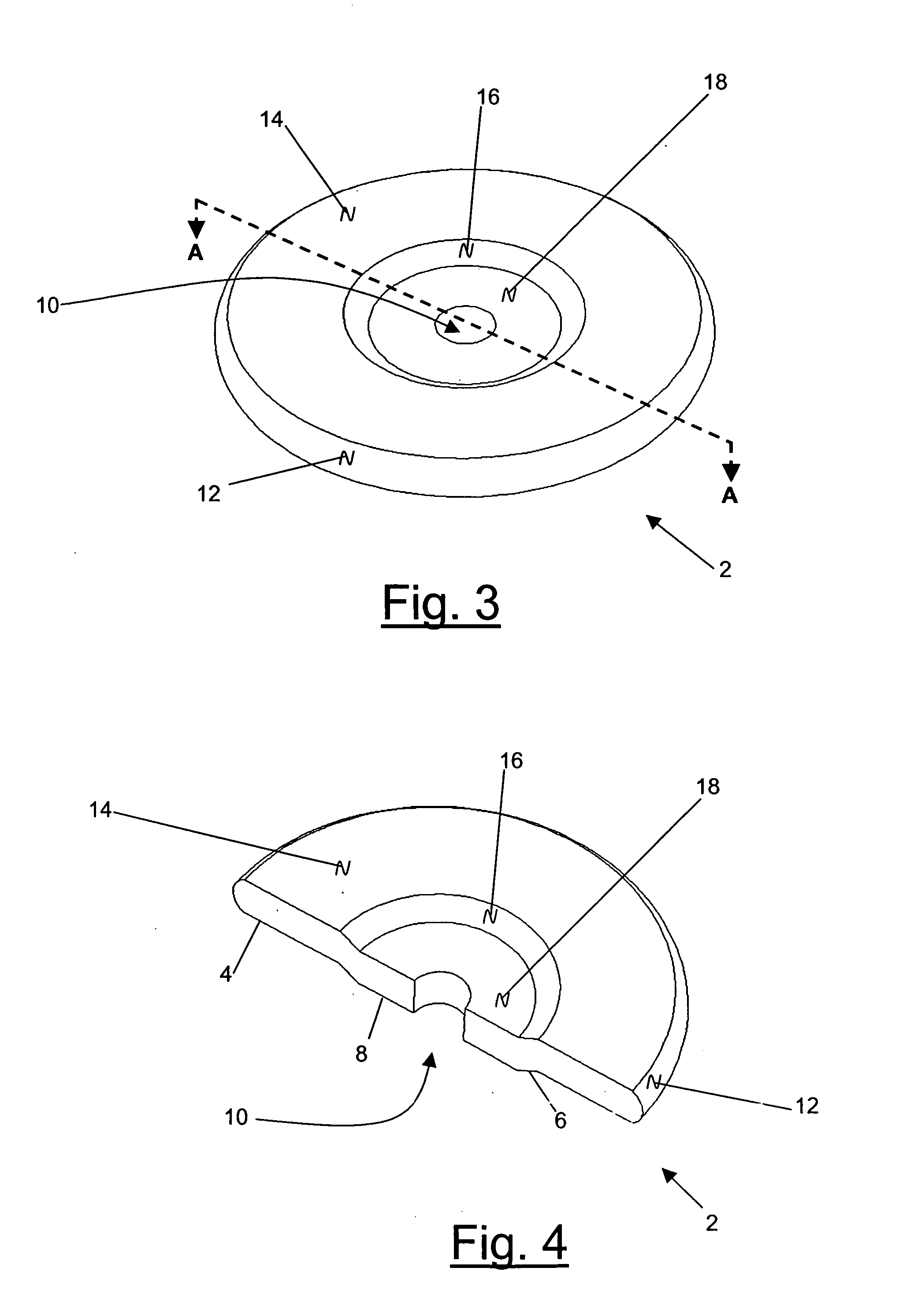
[0027] FIG. 1 is an exemplary perspective view of a top or front lateral face of a weight plate 2 in accordance with the present invention. The plate 2 is any entity of incremental mass to allow for graduation of lifting resistance. In general, weight plate 2 is comprised of a circular disc of varying thickness or density with rounded rims or edges 12 at its radial distal ends, and a circular central hole 10 at its radial center. The front lateral face or radial plane of the plate 2 is comprised of a conical protrusion 8 at a proximal end from its radial center, and a radial flat base 4 at a distal end thereof. The radial surface of the conical projection 8 along its radial longitudinal distal ends 6 bevel or slope radially downward towards the flat surface 4 of the plate 2. The conical projection 8, its oblique radial distal end surface 6, and the flat surface 4 of plate 2 are uniform, contiguous, and integral part of plate 2, forming a single piece. The cut-out section of plate 2 ...


PUM


Abstract

Stackable weight plates comprised of a front and a rear lateral faces with a protrusion at a proximal radial center of the front lateral face and corresponding recess at a proximal radial center of the rear lateral face is provided. The rear lateral face with the recess section at the proximal radial center of a top weight plate in a stack may rest (or be stacked) on the front lateral face with the protrusion at a proximal radial center of another weight plate. Because each plate is restrained along its center axis by the mating or interlocking of the protruded area of one plate with the recessed area of another weight plate, the stacked plates are therefore generally stable and do not fall due to lateral shearing of the stack. When mounted on a handle bar to form an inertial force exercise device, the recessed area of the rear lateral face of the weight plates of the present invention house the mounting or fastener mechanism.

Description

CROSS-REFERENCE TO RELATED APPLICATIONS[0001] The present application claims priority from related U.S. Provisional Patent Application Serial No. 60 / 417,310, filed Oct. 9, 2002, the entire disclosure of which is incorporated herein by reference.BACKGROUND OF THE INVENTION[0002] 1) Field of the Invention[0003] The present invention relates generally to exercise devices, and in particular to weight plates used in weight training.[0004] 2) Description of Related Art[0005] Dumbbells and barbells are inertial force exercise devices with dense body extremities or weight plates. They comprise of a central handle bar for griping the devices, with weight plates attached at or near both ends of the bar. In general, the weight plates may comprise of removable weight plates so that different or additional plates may be attached as desired to vary the weight of the device. Dumbbells and barbells with non-removable weight plates comprise of plates permanently attached to their central handle bar....

Claims


Application Information

Patent Timeline
IPC IPC(8): A63B21/06A63B21/072A63B21/075
CPCA63B21/06A63B21/0605A63B2209/08A63B21/075A63B21/0608
Inventor LANDFAIR, CRAIG D.
Owner LANDFAIR CRAIG D
Why Eureka
Try Eureka